Uncategorized

  • 02 Aug

    What Is Foam Filled Fender? The Ultimate Guide to Unsinkable Marine Protection

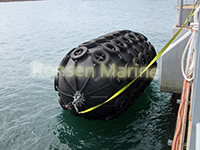
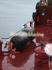
    When safety, durability, and low maintenance are top priorities, shipowners and port authorities turn to one solution: the foam filled fender. Also known as a solid polyurethane fender or EVA foam fender, this technology represents a major leap forward from traditional inflatable systems. But what exactly is it, and why is it considered “unsinkable”?

    This guide covers everything you need to know, from construction and working principles to technical specifications and real-world applications.

    What Is a Foam Filled Fender?

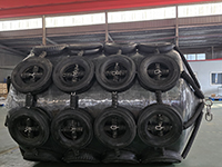
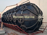
    A foam filled fender is a type of solid, floating marine fender that uses a closed-cell foam core as its energy absorption medium. Unlike pneumatic fenders that rely on compressed air, foam fenders are built around a core of expanded polyethylene (EVA) or polyurethane foam, encapsulated within a tough, reinforced polyurethane (PU) elastomer skin.

    Because the core is 100% closed-cell, it is impossible for the fender to sink, even if the outer skin is punctured. This makes it the preferred choice for mission-critical operations, including naval defense, offshore oil platforms, and high-traffic commercial ports.

    Construction & Working Principle

    The Core: High-Density Closed-Cell Foam

    The heart of the fender is its closed-cell EVA foam core. This material acts like a highly resilient sponge. Upon impact, the foam compresses, converting the kinetic energy of a berthing vessel into internal energy. Once the pressure subsides, the foam instantly rebounds to its original shape.

    Key Advantage: Even if the skin is compromised, the closed cells prevent water ingress, ensuring the fender remains buoyant and functional.

    The Skin: Reinforced Polyurethane Elastomer

    The core is protected by a thick layer of polyurethane (PU) or polyurea elastomer. This skin is spray-applied using high-pressure equipment, creating a seamless, waterproof barrier.

    Reinforcement: A spiral reinforcement layer (often utilizing nylon tire cords) is embedded within the skin to maximize tensile strength and puncture resistance.

    Performance: The PU skin offers exceptional resistance to abrasion, seawater corrosion, oil, and ultraviolet (UV) radiation.

    How It Absorbs Energy

    Foam filled fenders operate on the principle of compressive deformation. When compressed to 60% of its original diameter:

    Reaction Force: Increases progressively from low to high, minimizing stress on the vessel hull.

    Energy Absorption: Extremely high. Studies show foam fenders can absorb 1.2 to 1.5 times more energy than equivalent-sized pneumatic fenders.

    Foam Filled Fender vs. Pneumatic Fender

    Buyers often compare these two floating fender types. Here is how they stack up:

    Feature Foam Filled Fender Pneumatic (Yokohama) Fender
    Buoyancy Unsinkable(Watertight core) Floats(Risk of sinking if ruptured)
    Maintenance Zero (Maintenance-cree) Requires regular pressure checks
    Damage Response Puncture does not effect performance Requires immediate repair
    Weight 60%-70% lighter than steel alternatives Moderate weight

    Key Advantages of Foam Filled Fenders

    Unsinkable Design: The closed-cell foam core guarantees 100% buoyancy, eliminating the risk of losing equipment at sea.

    Maintenance-Free: No valves, no air pressure checks, and no risk of bursting. Install it and forget it.

    Extreme Durability: The polyurethane skin is highly resistant to scratches, friction, and impacts from rough berthing.

    Weather Resistance: Performs reliably in harsh environments, resisting acid, alkali, and extreme temperatures (-40°C to +70°C).

    Lightweight: Weighs significantly less than traditional rubber or steel fenders, simplifying handling and installation.

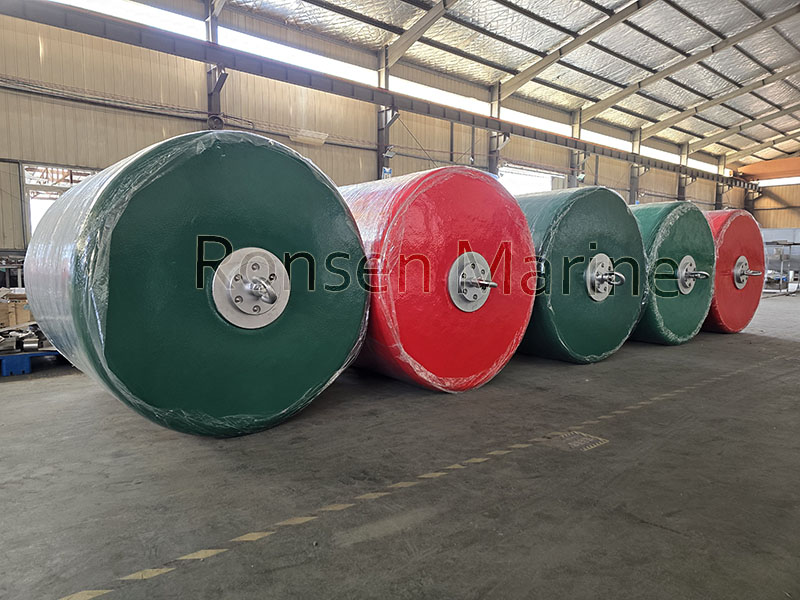
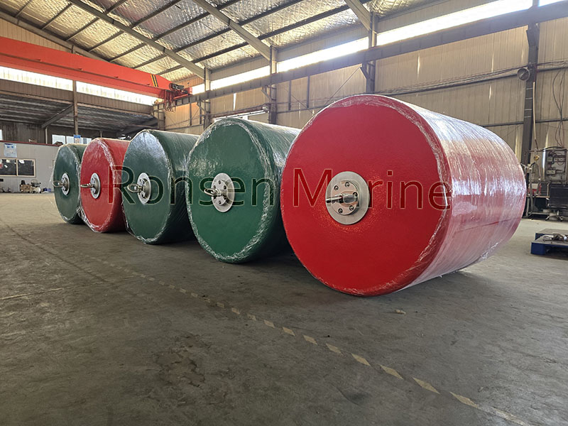
    Customizable: Available in virtually any size and color. Non-marking skins are available for white hulls (e.g., yachts, cruise ships).

    Technical Specifications & Classifications

    Types of Assembly

    Based on external fitting requirements, foam fenders are categorized into three main types:

    Sleeve Type: Features a protective chain or rubber sleeve.

    Sleeveless Type: Relies solely on the tough PU skin; ideal for clean hulls.

    Rotating Ear Type: Equipped with swivel lifting eyes for easy suspension.

    Standard Sizes

    We offer a full range of standard and custom sizes:

    Diameter (D): 0.5m to 3.3m (Custom sizes available up to 4.5m+)

    Length (L): 1.0m to 6.5m

    Performance: At 60% compression, reaction forces range from 1.5 tons to 160 tons, with energy absorption from 0.18 to 114 ton-meters.

    International Certifications

    Our foam filled fenders are manufactured under strict quality control and hold certifications from leading international classification societies:

    ✅ CCS (China Classification Society)

    ✅ BV (Bureau Veritas)

    ✅ DNV (Det Norske Veritas)

    ✅ ABS (American Bureau of Shipping)

    Performance in Extreme Conditions

    Effect of Temperature

    Polyolefin foams are engineered to perform across a wide thermal range.

    High Temperatures: In hot climates, foam may slightly soften. We recommend upsizing the fender by 5-10% for installations in extreme heat to compensate for reduced stiffness.

    Low Temperatures: In freezing conditions, the foam becomes stiffer, actually increasing its energy absorption capacity without compromising structural integrity.

    Effect of Compression Speed

    Foam fenders perform exceptionally well under dynamic loads. At high strain rates (fast berthing speeds), the foam core stiffens, allowing it to absorb significantly more energy than during slow, static compression. This ensures reliable protection even during high-speed emergency stops.

    Common Applications

    Thanks to their robust nature, foam filled fenders are used across the maritime industry:

    Naval & Military Berths: Ideal for navy vessels due to their unsinkable nature and low maintenance.

    Offshore Oil & Gas: Protecting platforms and tankers in open seas.

    Cruise & Ferry Terminals: Non-marking options protect expensive white hulls.

    Ship-to-Ship (STS) Transfers: Providing stable cushioning between moving vessels.

    Ports & Harbors: General cargo berthing and corner protection.

    Ro-Ro & Bulk Carriers: Handling heavy loads and frequent traffic.

    FAQ: People Also Ask

    Q: Can a foam filled fender really sink?

    A: No. The core is made of 100% closed-cell foam. Unlike pneumatic fenders that lose buoyancy if punctured, foam fenders remain afloat and operational even if the outer skin is damaged.

    Q: How long do foam filled fenders last?

    A: The service life is typically 10 to 15 years. With proper care and suitable environmental conditions, many high-quality foam fenders can last up to 30 years.

    Q: Do foam fenders leave black marks on ships?

    A: Standard fenders may leave slight marks, but we offer non-marking (white) polyurethane skins specifically designed for cruise ships, yachts, and other vessels with light-colored hulls.

    Q: What is the difference between EVA foam and Polyurethane foam?

    A: EVA (Ethylene-Vinyl Acetate) foam is generally lighter and offers excellent flexibility and rebound. Polyurethane foam is often denser and can offer higher load-bearing capacity. Both are used in high-performance marine fenders.

    Q: Are foam filled fenders heavier than pneumatic ones?

    A: They are denser than air-filled fenders but significantly lighter (60-70% lighter) than comparable steel fenders, making them relatively easy to handle with standard port equipment.

    Conclusion

    A foam filled fender is more than just a bumper—it is a strategic investment in safety and operational efficiency. By combining a 100% closed-cell EVA core with a reinforced polyurethane skin, these fenders offer unmatched durability, zero maintenance, and the peace of mind that comes with an unsinkable design.

    Whether you are outfitting a naval base, an offshore platform, or a busy commercial port, foam filled fenders provide the resilient protection your assets deserve.

    Ready to specify the right fender for your project?

    Contact our marine engineering team today for a free technical consultation, detailed drawings, and a competitive quotation tailored to your specific berthing requirements.

    By Ronsen Marine Uncategorized
  • 02 Aug

    What Is The Marine Airbag Launch Ship Procedure? A Complete Step‑by‑Step Guide

    What Is Marine Airbag Launch Ship Procedure?

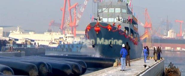
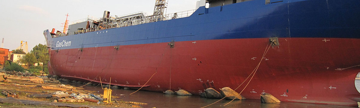
    The marine airbag launch ship procedure is a flexible, cost‑effective method of moving a newly built or repaired vessel from the shipyard slipway into the water using inflated cylindrical rubber airbags as rollers. Also known as airbag ship launching or inflatable roller bag launching, this technique replaces traditional dry docks or fixed slipways with portable, reusable marine airbags that bear the ship’s weight and allow it to roll smoothly into the water under controlled speed .

    Marine airbags are made of multi‑layer synthetic rubber reinforced with high‑tensile fabric. Once placed under the hull and inflated, they lift the vessel off its keel blocks and act as low‑friction rollers, enabling end‑on or side launching with minimal infrastructure .

    Advantages of the Marine Airbag Launching Method

    Before diving into the procedure, here’s why shipyards choose airbag launching:

    Lower cost – No permanent slipway or dry dock required

    Reusable equipment – Airbags can be used for multiple launches

    Adaptable – Suitable for small boats to large cargo vessels

    Reduced hull stress – Even load distribution and shock absorption

    Eco‑friendly – Minimal land alteration and seabed disturbance

    Pre‑Launch Preparation (Site & Equipment Checks)

    A safe launch begins long before inflation. Key preparatory steps include:

    1. Hull Inspection – Grind down sharp welds, burrs, or protruding fittings on the hull bottom. Close all sea valves, thrusters, and hull openings.
    2. Slipway Preparation – Level the launch path, remove nails, stones, or debris that could puncture airbags. Cross‑slope error should typically be <80 mm for small vessels and <50 mm for larger ones.
    3. Water Depth Check – Ensure sufficient water depth (commonly ≥1.5× the ship’s draft) at the entry point to prevent grounding.
    4. Airbag Selection & Inspection – Choose airbags with adequate diameter, length, and safety factor (typically 1.5–2× vessel weight). Inspect for cracks, leaks, or valve damage.

    5. Rigging & Winch Setup – Install holding winches, wire ropes, pulleys, and ground anchors to control vessel movement. Test compressors and hoses.


    Step‑by‑Step Marine Airbag Ship Launching Procedure

    Step 1: Position the Airbags

    Place deflated marine airbags transversely (perpendicular to the launching direction) under the keel at calculated intervals. Spacing depends on vessel length, weight, and airbag load capacity. Extra airbags may be added under heavier mid‑ship sections .

    Step 2: Inflate the Airbags & Lift the Hull

    Connect air hoses to the compressors. Inflate gradually (typical working pressure 0.03–0.08 MPa / 0.3–0.8 kg/cm² depending on size). As pressure builds, the airbags lift the hull evenly off the wooden keel blocks. Remove all blocks once the hull is fully supported by airbags .

    ⚠️

    Never exceed the airbag’s maximum rated pressure. Use a calibrated pressure gauge throughout.

    Step 3: Adjust Pressure & Align the Vessel

    Fine‑tune individual airbag pressures to keep the hull level. Misaligned or uneven pressure can cause tilting or airbag damage. Ensure airbags remain perpendicular to the launch path and do not twist during movement .

    Step 4: Controlled Rolling Toward the Water

    With the holding winch keeping the vessel stationary, release the brake slowly to let the ship roll forward on the inflated airbags. Typical forward speed is 0.5–1 m/s (≈6–13 m/min), controlled by winch tension. Use guide ropes if the vessel tends to veer off course .

    Step 5: Final Launch Into the Water

    When the hull reaches the water entry point, continue controlled release until buoyancy takes over. For narrow waterways, maintain winch control throughout. For open areas, the final hold‑back wire may be released or cut at the appropriate moment .

    Step 6: Deflate, Recover & Inspect

    Once afloat:

    Slowly deflate airbags (below 0.03 MPa before disconnecting hoses).

    Recover airbags from the water, inspect for punctures or deformation.

    Clean, dry, and store airbags in a cool, shaded area.

    Check the vessel for watertight integrity and measure bow/stern draft .

    Key Safety Tips for Airbag Ship Launching

    👷 All personnel must wear helmets, life jackets, and anti‑slip footwear.

    🚧 Keep non‑essential staff out of the launch zone.

    🌬️ Avoid launching in wind speeds above Beaufort Force 6, heavy rain, or rough seas.

    🔧 Install pressure relief valves on compressors to prevent over‑inflation.

    📋 Conduct a pre‑launch risk assessment and toolbox talk .

    FAQ: Common Questions About Marine Airbag Launch Procedure

    Q: Can marine airbags be used for any size ship?

    A: Yes. With proper calculation of airbag diameter, length, quantity, and safety factor, airbags can launch vessels from small fishing boats to large ocean‑going ships .

    Q: What slope is required for an airbag launch slipway?

    A: Typical slopes range from 1:7 to 1:15, depending on vessel size and site conditions .

    Q: How are airbags arranged under the hull?

    A: Common layouts include single‑row linear, staggered, or double‑row arrangements, chosen based on beam width and airbag effective length .

    Conclusion

    So, what is marine airbag launch ship procedure? It is a systematic, engineer‑led process involving site preparation, calculated airbag placement, controlled inflation, gradual hull lifting, winch‑controlled rolling, and safe water entry—followed by recovery and inspection. When executed with proper planning and safety protocols, marine airbag launching offers shipyards a flexible, economical, and reliable alternative to traditional launching methods.

    ISO 14409- Ship Launching Marine Air Bags

    Pneumatic Rubber Fenders

    Foam Filled Fenders

    By Ronsen Marine Uncategorized
  • 02 Aug

    What Is Foam Fender Classification? Types, Grade & PIANC Standards

    What Is Foam Fender Classification?

    Foam fender classification refers to the systematic categorization of foam‑filled marine fenders based on their external protection system, geometric shape, energy‑absorption performance, and compliance with international design standards. Also known as foam‑filled fender types or foam fender categories, this classification helps port authorities, marine engineers, and ship operators select the correct fender for specific berthing energies, vessel sizes, and environmental conditions.

    A foam‑filled fender typically consists of three layers: a closed‑cell polyethylene (PE) or EVA foam core, a nylon‑filament reinforcement layer, and a polyurethane (PU) or polyurea elastomer skin. Classification focuses primarily on how the outer protection and shape are configured to handle impact, abrasion, and hull pressure.

    Why Foam Fender Classification Matters

    Choosing the wrong fender type can lead to premature wear, higher lifecycle costs, or even operational downtime. Proper classification ensures:

    ✅ Correct energy absorption (EA) and reaction force (RF) matching

    ✅ Reduced hull damage and marking

    ✅ Lower maintenance in harsh or high‑traffic environments

    ✅ Compliance with PIANC WG211 and ASTM testing protocols

    1. Classification by External Protection System

    The most common and practical way to classify foam fenders is by their outer protective layer.

    A. Net‑Type Foam Fenders (Chain & Tire Net)

    These fenders are encased in a protective net made of steel chains and recycled rubber tires.

    Key Features: Extremely high abrasion resistance; sacrificial layer absorbs surface wear before it reaches the PU skin.

    Best For: Bulk cargo terminals, ore/coal ports, tug berths, and workboat docks where rough hulls or heavy contact occur.

    Trade‑Off: Heavier, more complex to install, and may mark softer hulls.

    B. Rope‑Net Foam Fenders

    Instead of steel chains, these use high‑strength synthetic fiber ropes (often nylon or polyester).

    Key Features: Lighter than chain‑net versions; softer contact with vessel hulls; moderate abrasion protection.

    Best For: Small‑to‑medium ports, yacht marinas, passenger terminals where hull aesthetics matter.

    Trade‑Off: Less durable in extremely aggressive industrial environments.

    C. Skin‑Only (Netless / Coated) Foam Fenders

    No external net—protection relies entirely on a thick, high‑performance PU or polyurea coating sprayed directly over the foam core and reinforcement.

    Key Features: Smooth, non‑marking surface; easiest to inspect and clean; lowest weight.

    Best For: Medium‑duty berths, floating pontoons, cruise ship terminals, naval vessels.

    Trade‑Off: Dependent on coating quality; less resistant to sharp or abrasive contact.

    Foam Fender Classification Comparison: Net‑Type vs Rope‑Net vs Skin‑Only
    Aspect Net‑Type Foam Fender Rope‑Net Foam Fender Skin‑Only (Netless) Foam Fender
    Abrasion Resistance Very High Medium Medium
    Hull Friendliness Medium High High
    Weight High Medium Low
    Maintenance Medium Low Very Low

    2. Classification by Shape / Configuration

    Foam fenders are also classified by their geometry and mounting method.

    Cylindrical Foam Fenders

    The most widely used type—available from 300 mm to 4,200 mm OD, suspended vertically from quay faces or floating freely between vessels. Ideal for general port berthing and ship‑to‑ship (STS) transfer.

    Donut (Toroidal) Foam Fenders

    Ring‑shaped fenders that slide over a tubular pile and rotate freely with tidal changes.

    Key Features: Self‑centering, floating, minimal adjustment needed.

    Best For: Breasting dolphins, bridge piers, lock entrances, ferry terminals.

    Boat‑Fender (Hull‑Mounted) Foam Fenders

    Continuous or segmented foam rings permanently bonded around a vessel’s hull (tugs, pilot boats, CTVs). Puncture‑proof and custom‑engineered to hull geometry.

    3. Classification by Performance Grade (Energy Absorption)

    Manufacturers classify foam fenders into performance grades based on foam core density and targeted energy absorption at 60% deflection (standard compression):

    • Standard (STD) Grade: Baseline energy absorption for normal commercial berthing.
    • High‑Capacity (HC / HC+) Grade: Increased foam density and reinforced skin for higher berthing energies (bulk carriers, VLCCs).

    💡 Note: When comparing grades, multiply the STD energy value by the manufacturer’s grade ratio (commonly 1.3×–1.5× for HC grades).

    4. Classification by International Standards

    Professional classification also references design and testing standards:

    • PIANC WG211 (2024): Guidelines for fender system design, energy absorption calculations, reaction force limits, and testing protocols. Recommends hull pressure below 200 kN/m² for most vessel types.
    • ASTM F2192: Standard test method for determining berthing energy and reaction force.
    • ASTM D2240: Measures polyurethane hardness (Shore A durometer), typically 75–95 Shore A for foam‑fender skins.


    How to Choose the Right Foam Fender Classification

    Selecting the correct classification depends on:

    1. Berthing Energy & Vessel Size – Higher energy favors net‑type + HC grade.
    2. Hull Condition – Rough/reinforced hulls increase abrasion risk → chain‑net.
    3. Traffic Frequency – High‑contact terminals benefit from sacrificial nets.
    4. Aesthetic Requirements – Passenger/cruise terminals → skin‑only/netless.
    5. Maintenance Capability – Remote sites → low‑maintenance skin‑only designs.
    6. Environmental Factors – Temperature range (PU skin typically -40°C to +60°C), UV exposure, chemical splash.

    FAQ: Common Questions About Foam Fender Classification

    Q: Are foam fenders classified the same way as pneumatic fenders?

    A: No. Pneumatic fenders are classified by internal air pressure and type (e.g., Yokohama‑type), while foam fenders are classified by external protection, shape, and foam‑core performance grade.

    Q: Can a skin‑only foam fender be used in an oil terminal?

    A: Generally not recommended. Oil terminals and container berths typically require chain‑net protection due to higher impact energy and abrasive conditions.

    Q: What is the typical service life of each classification?

    A: With proper inspection, net‑type and rope‑net fenders often exceed 10–15 years; skin‑only fenders may require recoating after 8–12 years depending on UV and abrasion exposure.

    Conclusion

    So, what is foam fender classification? It is the organized system of categorizing foam‑filled marine fenders by external protection (chain‑net / rope‑net / skin‑only), shape (cylindrical / donut / boat‑fender), performance grade (STD / HC), and compliance with PIANC WG211 and ASTM standards. Understanding these classifications enables engineers and port operators to match fender specifications precisely to berthing conditions—reducing damage, maintenance costs, and downtime.

    Pneumatic Fender

    Marine Airbag

    Foam Filled Fender

    By Ronsen Marine Uncategorized
  • 02 Aug

    Floating Yokohama Pneumatic Rubber Fenders: P50/P80 Specs & Selection Guide

    1. What Are Floating Yokohama Pneumatic Rubber Fenders?

    Floating Yokohama Pneumatic Rubber Fenders are advanced marine buffers designed to absorb the kinetic energy of vessels during berthing and ship-to-ship (STS) transfers. Originally pioneered by the Yokohama Rubber Company, these “Yokohama-type” fenders utilize compressed air as the primary energy-absorbing medium. Unlike solid rubber fenders, they feature a hollow, air-filled structure that allows them to float freely on the water’s surface, adapting seamlessly to tidal fluctuations and varying vessel drafts.

    Their core advantage lies in delivering exceptionally low reaction forces to the vessel hull while maintaining high energy absorption capabilities, making them indispensable for protecting mega-structures like VLCCs, LNG carriers, and offshore platforms.

    2. Core Construction: The Multi-Layer Architecture

    yokohama pneumatic rubber fender cross section

    To withstand the immense pressures of marine environments, a high-quality Yokohama fender is constructed with a sophisticated, multi-layered design:

    Outer Rubber Layer: This is the first line of defense. Made from a specialized synthetic rubber compound, it provides robust resistance against abrasion, ultraviolet (UV) radiation, and corrosive seawater.

    Synthetic-Tire-Cord Reinforcement Layer: Acting as the “skeleton” of the fender, this layer consists of crisscrossed nylon or aramid cords. This reinforcement ensures the fender maintains its structural integrity under high internal pressure and prevents bursting.

    Inner Rubber Layer: Seamlessly sealed to retain compressed air, this layer ensures zero leakage and consistent performance over the fender’s lifecycle.

    End Flanges and Safety Valves: Equipped with airtight flanges and a critical safety valve (especially on units with a diameter of 2.5 meters or larger) to automatically release excess pressure and prevent catastrophic failure.

    3. Key Classifications: Sling-Type vs. Chain & Tire Net (CTN)

    Choosing the right external protection system is crucial for extending the service life of your fenders. There are two primary configurations:

    Type I: Chain & Tire Net (CTN) Fenders

    These fenders are encased in a heavy-duty network of chains and used tires. This configuration offers maximum durability in aggressive environments.

    Best For: High-traffic ports, rough berthing conditions, and large-scale ship-to-ship transfers.

    Pros: Superior resistance to external abrasion and cutting; protects the rubber body from direct impact.

    Type II: Sling-Type Fenders

    Designed without an external chain net, these fenders are secured using heavy-duty slings or ropes attached to the end flanges.

    Best For: Lighter vessels, calm waters, and applications where hull marking must be avoided.

    Pros: Lightweight, easier to handle, and more cost-effective for general-purpose use.

    4. Technical Specifications: Decoding P50 and P80 Ratings

    The performance of a pneumatic fender is primarily dictated by its initial internal pressure, standardized under ISO 17357-1:2014:

    SpecificationP50 (Pneumatic 50)P80 (Pneumatic 80)
    Initial Internal PressureWorking pressure at 20°C50 kPa
    7.25 psi
    80 kPa
    11.6 psi
    Primary ApplicationTypical use caseStandard Commercial BerthingGeneral cargo, mid-size vesselsHigh-Energy OperationsLarge tankers, VLCCs, LNG carriers
    Energy Absorption (GEA)At 60% deflectionHighUltra-High≈ 1.3× – 1.5× higher than P50
    Reaction ForcePeak load on hullLowMinimal hull stressModerate to HighVerify vessel structural capacity

    Engineering Insight: While P80 fenders offer superior energy absorption, they also exert higher reaction forces on the vessel’s hull. It is critical to match the fender’s pressure rating with the structural capacity of the berthing vessel to prevent hull damage.

    5. How to Select the Right Fender Size

    Proper sizing requires calculating the Guaranteed Energy Absorption (GEA). A simplified selection guide based on vessel displacement is as follows:

    Vessel Tonnage (DWT)     Recommended Size (Diameter x Length)

    500 – 1,000 tons                                    1.0m x 1.5m to 1.2m x 2.0m

    1,000 – 5,000 tons                                 1.5m x 3.0m to 2.0m x 3.5m

    10,000 – 50,000 tons                              2.5m x 4.0m to 3.0m x 5.0m

    80,000+ tons (VLCC/LNG)                     3.3m x 6.5m or larger

    6. Maintenance and Safety Protocols

    To maximize the ROI of your floating fenders, adhere to these maintenance best practices:

    Pressure Monitoring: Regularly check internal pressure with a calibrated gauge. Deviations of more than 10% from the initial setting indicate a leak.

    Visual Inspections: Every 3 to 6 months, inspect the outer rubber for deep cuts, the chain net for rust, and the safety valve for blockages.

    Cleaning: Rinse fenders with fresh water after prolonged exposure to saltwater to prevent salt crystallization and rubber degradation.

    Storage: When not in use, store fenders in a cool, shaded area. Deflate them to approximately 20-30% of their working pressure to relieve stress on the rubber layers.

    Pneumatic Fender

    Marine Airbag

    By Ronsen Marine Uncategorized
  • 02 Aug

    Pneumatic Rubber Fenders: The Complete Guide for Marine Engineers & Port Buyers (2026)

    Quick Answer: What Are Pneumatic Rubber Fenders?

    A pneumatic rubber fender—often called a Yokohama fender—is a floating, cylindrical marine fender inflated with compressed air that acts as a shock absorber between two vessels (STS) or between a vessel and a dock (STD). Its reinforced-rubber body compresses under impact, using air compression to absorb berthing energy while keeping reaction force and hull pressure extremely low. Pneumatic fenders are the global standard for ship-to-ship transfers, LNG berthing, and offshore platforms because they automatically follow tidal changes and vessel movement.

    Table of Contents

    1. How Pneumatic Rubber Fenders Work (The Air-Spring Principle)
    2. Internal Structure: 4 Engineered Layers
    3. Key Advantages Over Solid & Foam Fenders
    4. P50 vs P80: Which Initial Pressure Rating to Choose
    5. Types: Net Type vs Sling Type vs Hydro-Pneumatic
    6. Standard Sizes & ISO 17357-1:2014 Performance Tables
    7. Pneumatic vs Foam-Filled vs Cell Fender Comparison
    8. How to Select the Right Pneumatic Fender
    9. Installation, Inflation & Maintenance Best Practices
    10. Service Life & Storage Guidelines
    11. FAQ: People Also Ask
    12. Conclusion & Next Steps

    1. How Pneumatic Rubber Fenders Work (The Air-Spring Principle) {#how-pneumatic-rubber-fenders-work}

    The working principle is based on air compression. When a vessel makes contact:

    1. The fender’s rubber body deforms and internal air pressure rises.
    2. Kinetic energy from the vessel is absorbed gradually as the air compresses.
    3. Reaction force stays relatively low and stable thanks to the “air spring” effect.
    4. At 60% deflection (the ISO 17357 standard test point), energy absorption peaks while hull pressure remains within safe limits.
    5. Once the load is removed, the air expands and the fender returns to its original shape.

    Because they float on the water surface, pneumatic fenders automatically adjust to tidal changes and vessel roll/pitch—something fixed fenders like cell or cone fenders cannot do.

    2. Internal Structure: 4 Engineered Layers {#internal-structure}

    A high-quality pneumatic fender is not just a rubber balloon—it’s a precision-engineered laminate:

    LayerMaterialFunctionOuter RubberAbrasion-resistant natural/synthetic rubber compoundProtects inner layers from UV, seawater, impact, and chafingCord Fabric LayerSynthetic tire-cord fabric (nylon/polyester) wound at precise anglesProvides tensile strength; prevents bursting under pressureInner RubberAirtight, low-permeability rubberSeals compressed air inside; prevents leakageEnd Flanges & FittingsGalvanized or stainless steel with air/safety valvesAllows inflation/deflation and secure lifting/anchoring

    Most reputable fenders comply with ISO 17357-1:2014 and carry third-party certification (BV, ABS, CCS, DNV, LR).

    3. Key Advantages Over Solid & Foam Fenders {#key-advantages}

    Extremely low hull pressure – Typically under 25 kN/m², safe for LNG, chemical, and coated hulls.

    High energy absorption with low reaction force – Ideal for sensitive vessels and lightweight berthing structures.

    Floating & tide-adaptive – Automatically follows tidal swings and vessel movement.

    Large contact area – Conforms to curved or irregular hull shapes, spreading impact evenly.

    Easy to deploy & relocate – Can be moved between berths or vessels as needed.

    Proven for STS operations – The industry standard for ship-to-ship cargo transfer and offshore lightering.

    4. P50 vs P80: Which Initial Pressure Rating to Choose {#p50-vs-p80}

    Pneumatic fenders come in two standard initial internal pressures per ISO 17357-1:2014:

    ParameterP50 (50 kPa)P80 (80 kPa)Energy absorptionBaseline (ISO GEA)~20–30% higher than P50 at same sizeReaction forceLowerHigherHull pressureLower – ideal for sensitive hullsHigher – check hull limitsFender size for same EALarger diameter neededSmaller diameter possibleBest use casesSheltered berths, STS, general cargoOffshore STS, VLCC/LNG, tight spacesMaintenanceEasier, more forgivingStricter – needs regular pressure checks

    Pneumatic Rubber Fender — Layer Structure

    4 Engineered Layers · ISO 17357 Compliant</p >

    Layer Material Function
    1Outer Rubber
    Protective Layer
    Abrasion-resistant natural/synthetic rubber compoundRubber Compound Protects inner layers from UV, seawater, impact, and chafing
    2Cord Fabric Layer
    Reinforcement Layer
    Synthetic tire-cord fabric (nylon/polyester) wound at precise anglesTire-Cord Fabric Provides tensile strength; prevents bursting under pressure
    3Inner Rubber
    Airtight Seal Layer
    Airtight, low-permeability rubberSealant Rubber Seals compressed air inside; prevents leakage
    4End Flanges & Fittings
    Hardware Layer
    Galvanized or stainless steel with air/safety valvesSteel + Valves Allows inflation/deflation and secure lifting/anchoring

    Engineering Note: All four layers work as an integrated system. Failure in any single layer compromises the entire fender’s performance and safety. Compliant with ISO 17357-1:2014; third-party certifications available (BV, ABS, CCS, DNV, LR).</p >

    Rule of thumb: Choose P50 if hull pressure is your constraint (LNG, aluminum, yacht, naval). Choose P80 if you’re tight on space and need maximum absorption per fender—but verify your hull/dock can take the extra reaction force.

    ⚠️ Never overinflate a P50 fender to 80 kPa. The reinforcement layers and safety factors are different between the two designs.

    5. Types: Net Type vs Sling Type vs Hydro-Pneumatic {#types-of-pneumatic-fenders}

    🔹 Chain-Tire Net (CTN) Type

    Protective net of chains and used aircraft tires. Extremely durable for heavy STS and rough environments. Downside: tires can scuff delicate hull paint.

    🔹 Sling Type

    Heavy-duty nylon straps instead of chains/tires. Gentler on hull coating—preferred for yachts, navy vessels, and LNG where surface finish matters.

    🔹 Rope Net Type

    Rope protection net offering a balance between weight and durability. Often used for mid-sized vessels.

    🔹 Hydro-Pneumatic Type

    Partially submerged, designed for submarines and vessels with very low freeboard. Not covered by ISO 17357-1 (falls under separate specifications).

    6. Standard Sizes & ISO 17357-1:2014 Performance Tables {#standard-sizes}

    Common ISO 17357 pneumatic fender sizes:

    📊 ISO 17357-1:2014 Performance Table

    Pneumatic Rubber Fender · Guaranteed Energy Absorption & Reaction Force at 60% Deflection 🌐 ISO 17357-1:2014 Compliant

    Nominal Size
    (Ø × L, mm)
    P50 (50 kPa) P80 (80 kPa)
    GEA (kJ) R (kN) GEA (kJ) R (kN)
    500 × 1000 6 64 8 85
    1000 × 1500 32 182 45 239
    1000 × 2000 45 257 63 338
    2000 × 3500 308 875 430 1,150
    2500 × 4000 663 1,381 925 1,815
    3300 × 6500 1,814 3,015 2,532 3,961
    4500 × 9000 4,755 5,988 6,633 7,551

    GEA = Guaranteed Energy Absorption (kJ) · R = Reaction Force (kN) · All values measured at 60% deflection per ISO 17357-1:2014.
    P50 fenders operate at 50 kPa initial internal pressure; P80 fenders at 80 kPa. Never overinflate a P50 fender to 80 kPa — the reinforcement design differs between the two.

    P50 — Standard Pressure (50 kPa)

    P80 — High Pressure (80 kPa)

    All values at 60% deflection per ISO 17357-1:2014. GEA = Guaranteed Energy Absorption; R = Reaction Force.

    💡 Sizing insight: A Ø3.3m × L6.5m P80 fender absorbs ~2,532 kJ at 60% deflection—enough for VLCC-to-VLCC side-by-side transfer. Always verify with manufacturer performance curves, not just dimensional tables.

    7. Pneumatic vs Foam-Filled vs Cell Fender Comparison {#comparison-table}

    Source synthesis from industry references.

    8. How to Select the Right Pneumatic Fender {#selection-guide}

    Step 1: Calculate Berthing Energy (E)

    Use the PIANC methodology:

    E = \frac{1}{2} M_e V^2 C_e C_m C_s C_c

    Where:

    • M_e = Effective displacement (vessel mass + added mass of water)
    • V = Approach velocity (typical 0.10–0.30 m/s for large vessels under tug assist)
    • C_e, C_m, C_s, C_c = Eccentricity, virtual mass, softness, and berth configuration coefficients

    Step 2: Define Constraints

    • Allowable hull pressure (check classification society rules)
    • Berth structure reaction-force limit
    • Tidal range and dolphin height
    • Environmental exposure (waves, currents, temperature)

    Step 3: Match to Performance Curve

    Select fender size so that absorbed energy ≤ GEA at 60% deflection, with reaction force ≤ hull/structure limits.

    Step 4: Choose Type & Accessories

    • STS heavy duty → CTN type, P80
    • Yacht/naval → Sling type, P50
    • Submarine → Hydro-pneumatic

    ⚠️ Common mistake: Specifying based on dimensional size alone. Two fenders with the same Ø×L can have vastly different energy absorption if pressure ratings differ. Always use ISO performance tables.

    9. Installation, Inflation & Maintenance Best Practices {#installation-maintenance}

    Pre-Deployment Checklist:

    ✅ Inflate with clean, dry air or nitrogen to rated initial pressure

    ✅ Verify safety relief valve functions correctly

    ✅ Inspect chain/tire net or sling for corrosion, wear, or loose connections

    ✅ Confirm end-flange bolts and shackles are tightened to spec

    Routine Maintenance:

    • Pressure checks: Monthly or before each operation. Temperature changes affect pressure—hot sun can raise pressure 10–15%.
    • Visual inspection: Check for cuts >1 cm deep, exposed cord fabric, valve leakage, or tire-net wear.
    • Cleaning: Rinse with fresh water after heavy fouling to remove salt/silt.
    • Valve service: Replace valve cores every 6 months in high-use environments.

    Storage (when not in use):

    • Deflate partially or fully
    • Store in cool, dry, well-ventilated area away from direct sunlight and ozone sources (electric motors, welding equipment)
    • Keep away from sharp objects and chemicals

    10. Service Life & Storage Guidelines {#service-life}

    With proper maintenance, a high-quality pneumatic fender typically lasts 10–15 years. Factors affecting lifespan:

    ✅ Keeping internal pressure within ±5% of rated

    ✅ Rinsing after heavy fouling

    ✅ Storing deflated + shaded when idle

    ✅ Inspecting tire-nets/chains for corrosion

    Replace immediately if:

    • Cuts expose cord fabric
    • Air leakage cannot be stopped by valve service
    • Permanent deformation exceeds manufacturer tolerance

    11. FAQ: People Also Ask {#faq}

    Q: Are pneumatic fenders the same as Yokohama fenders?

    A: Yes. “Yokohama fender” is the industry tradename, named after The Yokohama Rubber Co., which pioneered them. Technically they are floating pneumatic rubber fenders.

    Q: Are pneumatic fenders ISO certified?

    A: Reputable manufacturers produce to ISO 17357-1:2014 (high-pressure) or ISO 17357-2 (low-pressure). Always request third-party certs (BV, ABS, CCS, DNV, LR).

    Q: Can pneumatic fenders be used on a fixed dock instead of cone fenders?

    A: They can, but usually shouldn’t if the berth is permanent and high-traffic. Pneumatics cost more to maintain (air checks, net wear) and can drift if not properly tensioned. Fixed docks typically do better with Super Cone or cell fenders, reserving pneumatics for STS or extreme tidal cases.

    Q: What’s the difference between pneumatic fenders and marine airbags?

    A: They are not interchangeable. Marine airbags are for ship launching and salvage (pure buoyancy + rolling). Pneumatic fenders are certified berthing devices with ISO performance tables. Different tool, different job.

    Q: How often should I inspect pneumatic fenders?

    A: At least quarterly, or after any major impact or severe weather event. High-traffic terminals may require monthly checks.

    Q: Can I repair a punctured pneumatic fender?

    A: Small cuts can be patched with cold-cure rubber patches. Large damage or cord exposure requires professional factory repair or replacement.

    12. Conclusion & Next Steps {#conclusion}

    Pneumatic rubber fenders remain the gold standard for floating, low-reaction-force marine protection—especially for ship-to-ship transfers, LNG terminals, and offshore platforms where fixed fenders cannot adapt to tidal and vessel movement. Selecting the right combination of size, pressure rating (P50/P80), and protection type (CTN/Sling/Hydro) requires matching berthing energy calculations to ISO 17357 performance curves—not guesswork.

    Need Help Sizing Your Pneumatic Fender System?

    Our marine engineering team can calculate berthing energy for your specific vessel class, recommend optimal Ø×L and pressure rating, and provide ISO 17357-compliant drawings and performance curves.

    👉 Download our Pneumatic Fender Sizing Worksheet

    👉 Request a free technical proposal and quotation

    Ship Launching Airbags

    Foam Filled Fenders

    By Ronsen Marine Uncategorized
  • 01 Aug

    What Is a Cone Rubber Fender? The Ultimate Guide for Marine Engineers (2026)

    Quick Answer: What Is a Cone Rubber Fender?

    A cone rubber fender is a high-performance marine fender with a conical shape that absorbs massive berthing impact energy while exerting low reaction force on both the vessel hull and the dock structure. Its unique truncated-cone geometry allows it to deflect up to 70% of its height, making it one of the most efficient fenders for large container ships, oil tankers, and LNG carriers at high-traffic ports.

    How Does a Cone Rubber Fender Work?

    When a vessel approaches a berth, the cone fender compresses axially and flexes radially. Its conical profile allows it to:

    • Absorb high impact energy by deflecting up to ~70% of its height without a sharp rise in reaction force.
    • Self-center under load, staying aligned even during oblique berthing angles (up to 10–15° off-axis).
    • Distribute loads evenly when paired with a steel frontal panel and UHMW-PE facing pad, reducing hull pressure and preventing marks.
    • Resist shear and torsion, making it ideal for locations with strong currents, tides, or frequent vessel movement.

    Most cone fenders are single-piece moldings made from marine-grade, UV- and seawater-resistant rubber compounds, often installed with pre-built-in bolts, chains, and frontal panels.

    Key Advantages of Cone Rubber Fenders

    Compared with traditional arch or cylindrical fenders, cone fenders offer several performance benefits:

    ✅ Highest energy absorption per unit size – smaller cones can replace larger cell or arch fenders, lowering project cost.

    ✅ Low reaction force – gentler on both quay walls and ship hulls.

    ✅ Excellent shear resistance – stable under oblique impacts and tidal movement.

    ✅ Long service life – marine-grade rubber compounds resist UV, ozone, and salt corrosion.

    ✅ Low maintenance – robust one-piece molding with minimal moving parts.

    ✅ Flexible installation – can be mounted normally or reversed on narrow structures.

    Typical Applications

    Cone rubber fenders are widely used in medium- to high-traffic terminals handling large vessels, including:

    • Container terminals and general cargo wharves
    • Oil, gas, and LNG berths
    • RoRo (roll-on/roll-off) and cruise terminals
    • Naval and offshore platform dolphins
    • Ports with large tidal ranges or frequent berthing cycles

    Cone Fender vs. Cell Fender: What’s the Difference?

    FeatureCone Rubber FenderCell Rubber FenderEnergy absorptionHigher (up to 70% deflection)Moderate (~52.5% deflection)Reaction forceLower at same energy levelHigherShear resistanceExcellent (conical geometry)GoodFrontal panel compatibilityOptimized for large panelsCompatibleSpace requirementCompact footprintSimilar

    Bottom line: If your priority is maximizing energy absorption while keeping reaction force low—especially with large panels or angled berthing—cone fenders are typically the better choice.

    Common Cone Fender Sizes & Customization

    Standard cone fenders range from roughly 300 mm to 1,500+ mm in height, with corresponding reaction-force and energy-absorption ratings tailored to specific berthing energies. Many suppliers offer:

    • Custom heights and diameters
    • Different rubber hardness grades (standard / intermediate / high-energy compounds)
    • Custom colors and mounting hardware
    • Pre-assembled kits with frontal panels, UHMW-PE pads, chains, and anchor bolts

    Always specify your vessel size, berthing angle, tidal range, and design energy when requesting a quotation.

    Maintenance, Inspection, and Longevity Practices

    Routine Inspection Checklists for Marine Operators

    Port authorities should establish a scheduled maintenance program to inspect their fendering assets at least once every six months. A standard inspection checklist should include:

    • Checking the rubber cone body for deep cuts, ozone cracking, or permanent deformation.
    • Inspecting all anchor bolts and chain shackles for signs of severe marine corrosion or loosening.
    • Measuring the remaining thickness of the UHMW-PE face pads to ensure they have not worn down to the steel panel bolts.
    • Verifying that weight support and tension chains maintain the correct amount of slack.

    Troubleshooting Common Wear Issues (Friction, Shear, and UV Damage)

    If an operator notices localized cracking near the base of the cone, it often indicates excessive shear stress caused by a broken tension chain. Accelerated wear on the UHMW-PE pads suggests high amounts of silt or rough hull surfaces scraping the berth. Replacing worn face pads early prevents metal-on-metal contact, preserving both the vessel hull and the internal steel frame from costly damage.

    Estimating and Extending the Service Life of a Cone Fender

    A premium, properly maintained cone fender system can easily achieve an operational lifespan exceeding 20 years. To maximize longevity, port operators should keep marine growth cleared from around the rubber base and ensure that chain assemblies remain properly adjusted. Investing in high-quality UV-stabilized rubber compounds during the initial procurement phase pays massive dividends by preventing premature environmental degradation.

    FAQ: Cone Rubber Fenders

    Q: What vessels are cone rubber fenders suitable for?

    A: They’re commonly used for container ships, bulk carriers, oil/LNG tankers, cruise ships, and naval vessels at medium-to-largeQ: How long does a cone fender last?

    A: With proper installation and occasional inspection, high-quality marine-grade cone fenders typically last 10–15+ years in harsh saltwater environments.

    Q: Do cone fenders require a frontal panel?

    A: While not strictly mandatory, most installations include a steel frontal panel with a UHMW-PE facing pad to spread hull pressure and reduce friction.

    Q: Can cone fenders be used on narrow jetties?

    A: Yes—cone fenders can be mounted in reverse (small face toward the quay) to fit structures with limited footprint.

    Q: Are cone fenders compliant with international standards?

    A: Reputable manufacturers produce cone fenders in accordance with standards such as PIANC Guidelines and ISO 17357.

    Conclusion

    A cone rubber fender is one of the most efficient, durable, and versatile solutions for protecting docks and vessels during berthing. Its conical geometry delivers industry-leading energy absorption with low reaction force, excellent shear resistance, and long-term reliability—making it a smart investment for modern port infrastructure.

    Need a Quote or Technical Proposal?

    If you’re planning a new terminal or upgrading an existing berth, our engineering team can help you select the right cone fender size, compound, and mounting system for your design energy and tidal conditions.

    👉 Contact us today for a free technical proposal and customized quotation.

    By Ronsen Marine Uncategorized
  • 28 Jul

    What Is Ship Launching Airbag? The Ultimate Guide to Marine Airbags

    Traditionally, building a new vessel meant constructing massive concrete slipways—a process that was expensive, time-consuming, and environmentally invasive. Today, shipyards around the world are adopting a revolutionary alternative: the ship launching airbag. But what exactly is a ship launching airbag, and why has it become the gold standard for modern shipbuilding?

    This guide explains the construction, working principles, and key advantages of marine rubber airbags, also known as “Yokohama-type launching airbags.”

    What Is a Ship Launching Airbag?

    A ship launching airbag is a large, cylindrical, inflatable device made from reinforced synthetic-tire-cord rubber. It is designed to lift a vessel off its support blocks and roll it safely into the water. Unlike rigid slipways, these airbags act as flexible rollers, adapting to the hull shape and distributing the vessel’s weight evenly across the ground.

    They are primarily used for:

    • Ship Launching: Moving newly built vessels from land to water.
    • Ship Landing/Docking: Pulling vessels ashore for repair without a dry dock.
    •  
    • Heavy Object Moving: Transporting heavy structures like bridges, caissons, and large tanks.

    The Core Construction: Multi-Layer Technology

    The durability of a ship launching airbag comes from its sophisticated multi-layer design. High-quality airbags, compliant with the ISO 14409 standard, typically consist of three main sections:

    1. Inner Rubber Layer (Airtight Seal)

    This inner layer maintains air tightness. It is made from high-quality natural rubber that remains flexible and impermeable under pressure. Its primary job is to prevent air leakage and protect the internal reinforcement layers from moisture.

    2. Synthetic-Tire-Cord Reinforcement Layer

    This is the backbone of the airbag. Multiple layers (typically 4 to 12 layers) of high-tensile synthetic tire cord fabric are wound around the core at specific angles (usually 54°44′ ± 2°). This crisscross pattern provides exceptional tensile strength and explosion-proof capabilities, allowing the airbag to withstand pressures exceeding 250 kPa.

    3. Outer Rubber Layer (Protective Skin)

    The outermost layer protects the internal structure from external damage. It is formulated to resist abrasion, aging, UV radiation, and acid/alkali corrosion. The thickness of this layer is critical—it determines how well the airbag can withstand friction against the ground and the ship’s hull during rolling.

    Cross-section diagram of a ship launching airbag showing inner rubber, synthetic tire cord layers, and outer protective skin

    Figure 1: Cross-section of a typical ship launching airbag structure.

    How Do Ship Launching Airbags Work?

    The physics behind airbag launching is straightforward but ingenious:

    1. Placement: Deflated airbags are placed beneath the vessel’s keel, perpendicular to the hull.
    2. Inflation: Airbags are inflated to a predetermined pressure (typically 0.05–0.15 MPa), lifting the vessel off its wooden support blocks.
    3. Removal of Blocks: Once the hull is fully supported by the airbags, the wooden blocks are removed.
    4. Launching: Using winches or gravity, the vessel begins to move. As the ship rolls forward, the airbags rotate, acting like a conveyor belt of giant rollers, smoothly transferring the vessel into the water.

    Key Specifications and Standards

    When sourcing airbags, it is crucial to understand the technical specifications. The international benchmark is ISO 14409:2011 (Ships and marine technology — Ship launching air bags).

    Parameter Typical Range Notes
    Diameter (D) 0.8m – 2.5m Larger diameters distribute pressure better.
    Effective Length (EL) 6.0m – 22.0m Determines the total load-bearing area.
    Layers (N) 4 – 12 plies More layers = higher safety factor & pressure rating.
    Safety Factor ≥ 4:1 Bursting pressure vs. working pressure.

    Advantages Over Traditional Slipways

    Why have thousands of shipyards switched to airbag technology?

    • Cost-Effective: Eliminates the need for expensive civil engineering (concrete ramps).
    • Space Saving: Allows launching in locations with limited infrastructure.
    • Versatility: Suitable for various vessel types, from small fishing boats to 100,000 DWT tankers.
    • Environmentally Friendly: Reduces concrete usage and ground disturbance.
    • Flexibility: Airbags can be deflated and moved easily, allowing for quick setup and takedown.

    Maintenance and Storage Best Practices

    To ensure a long service life (typically 6–8 years), proper maintenance is essential:

    • Cleaning: Rinse with fresh water after use, especially if used in saltwater or muddy areas.
    • Drying: Ensure the airbag is completely dry before storage to prevent mildew.
    • Powdering: Apply talcum powder to the outer surface to prevent the rubber layers from sticking together.
    • Storage: Store indoors in a cool, dry, and dark place, away from acids, alkalis, and sharp objects.

    Frequently Asked Questions (FAQ)

    Q: How much weight can a ship launching airbag support?

    A: The load capacity depends on the diameter, length, and number of reinforcing layers. A standard 1.5m x 12m airbag with 6 layers can typically support approximately 100–150 tons per linear meter under safe working pressure.

    Q: Are ship launching airbags safe?

    A: Yes, when used correctly and manufactured to ISO 14409 standards. The multi-layer synthetic-tire-cord construction provides a high safety factor (usually 4:1 or higher), making catastrophic failure extremely rare.

    Q: Can airbags be used for landing ships (hauling out)?

    A: Absolutely. The process is essentially the reverse of launching. Airbags are placed under the hull, inflated to lift the vessel, and then used to roll the ship onto land for repairs or maintenance.

    Q: What is the difference between launching airbags and salvage airbags?

    A: While similar in construction, salvage airbags are often designed with higher buoyancy-to-weight ratios and specific connection points for underwater lifting operations, whereas launching airbags are optimized for rolling friction and ground contact.

    Conclusion

    The ship launching airbag is more than just an inflatable bag; it is a sophisticated piece of marine engineering that has democratized shipbuilding. By offering a safe, economical, and flexible alternative to traditional slipways, it allows shipyards of all sizes to operate efficiently.

    Looking for ISO 14409 certified ship launching airbags? Ronsen Marine supplies high-performance marine airbags with DNV-GL, ABS, and CCS certifications. Contact our technical team</a > today for a customized calculation report and competitive pricing


    Related Reading: Ship Launching Airbags Pneumatic Rubber Fenders How to Install Ship Launching Airbags Safely

    By Ronsen Marine Uncategorized
  • 28 Jul

    Support Buoys

    Support Buoys: The Complete Guide to Offshore Mooring Buoys

    In offshore marine operations, reliability is everything. From Single Point Mooring (SPM) systems to subsea cable installations, support buoys provide the critical buoyancy needed to keep chains, hoses, and cables safely afloat. Choosing the wrong buoy can lead to equipment loss, downtime, and safety hazards.

    This guide explains what support buoys are, how they are constructed, the main types available, and how to select the right one for your offshore project.

    What Are Support Buoys?

    Support buoys are heavy-duty floating devices designed to support and protect marine infrastructure—primarily mooring chains, ropes, and hoses. Unlike small navigational markers, offshore support buoys must withstand high tensile loads, continuous wave action, UV exposure, and corrosive seawater.

    Modern foam-filled support buoys are virtually unsinkable, making them the preferred choice for mission-critical offshore applications.

    Support Buoy Construction: Why Foam-Filled Wins

    Premium marine support buoys, such as those manufactured by Ronsen Marine, use a three-layer closed-molding process:

    1. Core: Closed-Cell EVA/PE Foam

    The core consists of low-density polyethylene (PE) or Ethylene-Vinyl Acetate (EVA) foam. Its closed-cell structure ensures 100% watertight integrity—even if the outer skin is punctured, the buoy retains full buoyancy.

    2. Reinforcement: Nylon Tire Cord Layers

    Multiple layers of high-tenacity nylon tire cord fabric wrap the core, absorbing tensile stress from chains and preventing elongation under dynamic loads.

    3. Outer Skin: Polyurethane Elastomer

    The outer shell is a thick, seamless polyurethane (PU) elastomer coating that is:

    • Abrasion-resistant – withstands friction from chains and hulls.
    • UV-stable – prevents chalking and surface degradation.
    • Non-marking – optional colored PU avoids hull staining.

    Types of Support Buoys

    Selecting the correct type depends on your specific offshore application:

    A. Chain-Through Support Buoys (Cylindrical)

    These buoys feature a steel central tube, allowing the mooring chain to pass directly through the buoy.

    • Application: Used as chain-stopper buoys in SPM systems to support chain weight and reduce hawse-pipe tension.
    • Advantage: Excellent load distribution and stability in strong currents.

    B. Pick-Up Buoys (Cylindrical or Spherical)

    Smaller, lightweight buoys attached to mooring lines via pick-up ropes or chain plates.

    • Application: Retrieving submerged mooring lines, marking subsea assets, and providing auxiliary floatation.
    • Advantage: Easy handling and rapid deployment.

    C. Foam-Filled Support Buoys (General Purpose)

    Versatile buoys used across dredging, offshore wind, and cable-lay operations.

    • Application: Supporting suction hoses, marker buoys for turbines, and temporary mooring points.
    • Advantage: Unsinkable design and minimal maintenance.

    Key Applications of Offshore Support Buoys

    • Oil & Gas (SPM Systems): Mid-line chain support and tension reduction.
    • Subsea Cable Installation: Keeping power and fiber-optic cables afloat during lay operations.
    • Offshore Wind Farms: Marking turbine locations and guiding SOVs.
    • Dredging Operations: Supporting discharge pipes and suction hoses.
    • Defense & Ports: Temporary moorings and security barriers.

    How to Select the Right Support Buoy

    Follow these steps to specify the correct buoy:

    1. Calculate Required Buoyancy: Determine the submerged weight of the chain/rope plus desired freeboard.
    2. Match Chain Size: Ensure the central tube diameter fits your chain (e.g., 64mm, 76mm, 84mm).
    3. Assess Environmental Conditions: Factor in tidal range, current velocity, and wave height.
    4. Confirm Compliance: Verify alignment with PIANC guidelines and OCIMF recommendations.
    5. Choose Materials: Specify hot-dip galvanized or epoxy-coated steelwork for maximum corrosion resistance.

    Support Buoys vs. Marine Fenders: What’s the Difference?

    Although both float, their roles differ significantly:

    • Support Buoys: Provide flotation and tension relief for mooring lines and chains.
    • Marine Fenders: Absorb kinetic energy during vessel berthing to protect hulls and structures.

    For comprehensive protection, offshore projects often deploy both foam-filled support buoys and foam-filled marine fenders

    Maintenance Tips for Long-Term Performance

    • Inspect PU skins annually for deep cuts or abrasions.
    • Rinse buoys with fresh water after deployment in polluted or tropical waters.
    • Check galvanized steelwork for signs of corrosion every 12 months.
    • Store spare buoys in shaded, ventilated areas when not in use.

    Frequently Asked Questions (FAQ)

    Q: How long do foam-filled support buoys last?

    A: With proper inspection and care, high-quality foam-filled support buoys typically deliver 10–15 years of service life, thanks to UV-stable polyurethane skins.

    Q: Are support buoys truly unsinkable?

    A: Yes—when constructed with closed-cell EVA/PE foam cores. Unlike air-filled buoys, foam cores displace water permanently and remain afloat even after major skin damage.

    Q: Can support buoys be customized?

    A: Absolutely. Ronsen Marine offers customization in diameter, length, color (yellow, orange, red, green), and hardware (galvanized vs. stainless steel).

    Conclusion

    Investing in the right support buoys enhances safety, reduces downtime, and lowers lifecycle costs. Foam-filled, polyurethane-skinned buoys deliver unmatched reliability in the harshest offshore environments.

    Need support buoys for your next offshore project?
    Ronsen Marine supplies ISO-certified foam-filled support buoys worldwide. Contact our engineering team</a > today for technical drawings and a competitive quotation.


    Related Resources:
    Cylindrical Chain Support Foam Buoys
    Foam Filled Fenders
    What Is a Foam Filled Fender?

    By Ronsen Marine Uncategorized
  • 25 Jul

    What Is a Foam Filled Fender?

    Foam Filled Fenders

    Foam Filled Fender is a fender that features a polyurethane elastomer outer layer, a nylon fiber reinforcement layer, and a foam solid core layer serving as the filling layer, ensuring high buoyancy and zero water absorption.

    What’s the constructure of a foam filled fender?

    The fender consists of an outer layer of polyurethane elastomer, a nylon fiber reinforcement layer, and a foam core. The schematic diagram of the fender structure is shown below.

    Foam Filled Fender

    1. Outer polyurethane elastomer layer;
    2——Nylon fiber reinforcement layer;
    3——Foam solid core layer;
    4. Support inner pipe (optional);
    5—Flange structure;
    6——Tire guard (optional).
    L——Fender length, unit in millimeters (mm);
    Pφ —— Fender diameter, unit in millimeters (mm)

    What’s the classification?

    Foam Fenders can be divided into:a) Z-type – heavy-duty fender with high reaction force and high energy absorption under the same compression conditions.
    b) Q-type – lightweight fender with low reaction force and low energy absorption under the same compression conditions.

    What’s appearance quality?

    The surface of the fender should have a uniform texture and should not have defects such as foreign objects, bubbles, cracks, etc. that affect its performance.
    The filling material inside the fender should not be exposed.

    What’s the material?

    The physical properties of polyurethane layer elastomer materials shall comply with the provisions of Table 4.

    The nylon fiber reinforcement layer material can use 1400D2/V1 nylon, and its physical properties should comply with the specifications in Table 5.

    The physical properties of foam solid core material shall comply with the provisions in Table 6.


    hat’s the fender body tests?

    Appearance quality: Visual inspection is used for inspection

    Specifications and Dimensions: Use steel tape, steel ruler, and vernier caliper that meet the accuracy requirements for inspection

    Dimensional tolerance: Use steel tape, steel ruler, and vernier caliper that meet the accuracy requirements for inspection

    Mechanical Properties: Perform testing and calculation according to the method specified in Appendix A

    What’s the material test?
    The physical properties of polyurethane layer elastomer materials shall be determined in accordance with the relevant standards specified in Table 4.
    The physical properties of nylon fiber reinforced layer materials shall be determined in accordance with the relevant standards specified in Table 5.
    The physical properties of foam solid core material shall be determined according to the relevant standards in Table 6.

    What’s the type test?

    Timing of Inspection
    Type inspection should be conducted for fenders in any of the following situations:
    a) The first production product for trial production, finalization identification, and factory transfer production of new products;
    b) When there are significant changes in structure, materials, and processes that can affect product performance;
    c) When the product is discontinued for more than 6 months and production resumes;
    d) When the higher-level testing agency requires type inspection.

    What’s the transportation?

    Fenders should be kept clean during transportation.
    Prevent fenders from being dropped, bumped, dragged, or rolled.
    Prevent fenders from being hooked, suspended, pricked, or scratched by hard objects.
    Prevent the fender from coming into contact with substances such as acids, alkalis, oils, and organic solvents.

    What’s the storage?

    Fenders should be stored indoors at a temperature of -10 ℃ to 30 ℃, avoiding direct sunlight and exposure to rain and snow.
    Prevent the fender from coming into contact with substances such as acids, alkalis, oils, and organic solvents.
    The fender should be at least 1 meter away from the heat source.


    W

    By Ronsen Marine Uncategorized
  • 23 Jul

    What Is Support Buoy?

    Support Buoys

    Support buoys are produced from closed cell EVA/PE resilient foam, sprayed with self-colored polyurethane elastomer skin, are a kind of general surface support buoys for offshore mooring buoys system. They are widely used as the warning buoys for ships, vessels, barges and boats as well as marines docking & berthing. Support Buoys are normally classified into pick up buoys, chain through buoys, cylindrical buoys, anchor pendant buoys and mooring buoys etc.

    Support Buoys Construction

    • Closed cell resilient foam core, unsinkable design

    Cylindrical chain support foam buoys are manufactured with high density closed-cell PE/EVA resilient foam core. This resilient foam ensure buoys self fendering with high impact absorption capacity, even the polyurethane elastomer skin punctured, cylindrical chain support foam buoys will be unsinkable without absorbing any water.

    • Tough reinforced Nylon Layer
    Support Mooring Buoys

    Each cylindrical chain support foam buoy is constructed of polyurethane elastomer reinforced with nylon filament layer. The polyurethane skin is unique elastomer especially for offshore & subsea applications. The elastomer skin is high resistance to abrasion, fatigue and ultra violet degradation and significantly much more durable.

    • Excellent end steel works

    There is a central tube encased in the closed-cell urethane foam central body of cylindrical chain support foam buoys. The central tube is either epoxy coated or hot-dipped galvanized, with longitudinal gussets and extend load distribution flanges at each end. Optional accessories like bail eye, clevis eye, swivel, chain locking plate, single locking pin end fitting etc.

    Cylindrical Chain Support Foam Buoys Specification

    Cylindrical Buoys (RS-CB)

    Cylindrical Buoys Foam Buoys-RONSEN MARINE


    Chain Through Buoys (RS-CTB)

    Cylindrical Chain Through Buoys CTB - RONSEN MARINE


    Pick Up Buoys (RS-PUB)

    Pick Up Buoys Foam Buoys -RONSEN MARINE

    By Ronsen Marine Uncategorized
1 2 3