
1. What Are Floating Yokohama Pneumatic Rubber Fenders?
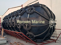
Floating Yokohama Pneumatic Rubber Fenders are advanced marine buffers designed to absorb the kinetic energy of vessels during berthing and ship-to-ship (STS) transfers. Originally pioneered by the Yokohama Rubber Company, these “Yokohama-type” fenders utilize compressed air as the primary energy-absorbing medium. Unlike solid rubber fenders, they feature a hollow, air-filled structure that allows them to float freely on the water’s surface, adapting seamlessly to tidal fluctuations and varying vessel drafts.
Their core advantage lies in delivering exceptionally low reaction forces to the vessel hull while maintaining high energy absorption capabilities, making them indispensable for protecting mega-structures like VLCCs, LNG carriers, and offshore platforms.
2. Core Construction: The Multi-Layer Architecture
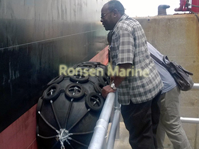
To withstand the immense pressures of marine environments, a high-quality Yokohama fender is constructed with a sophisticated, multi-layered design:
Outer Rubber Layer: This is the first line of defense. Made from a specialized synthetic rubber compound, it provides robust resistance against abrasion, ultraviolet (UV) radiation, and corrosive seawater.
Synthetic-Tire-Cord Reinforcement Layer: Acting as the “skeleton” of the fender, this layer consists of crisscrossed nylon or aramid cords. This reinforcement ensures the fender maintains its structural integrity under high internal pressure and prevents bursting.
Inner Rubber Layer: Seamlessly sealed to retain compressed air, this layer ensures zero leakage and consistent performance over the fender’s lifecycle.
End Flanges and Safety Valves: Equipped with airtight flanges and a critical safety valve (especially on units with a diameter of 2.5 meters or larger) to automatically release excess pressure and prevent catastrophic failure.
3. Key Classifications: Sling-Type vs. Chain & Tire Net (CTN)
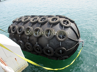 Choosing the right external protection system is crucial for extending the service life of your fenders. There are two primary configurations:
Type I: Chain & Tire Net (CTN) Fenders
These fenders are encased in a heavy-duty network of chains and used tires. This configuration offers maximum durability in aggressive environments.
Best For: High-traffic ports, rough berthing conditions, and large-scale ship-to-ship transfers.
Pros: Superior resistance to external abrasion and cutting; protects the rubber body from direct impact.
 Type II: Sling-Type Fenders
Designed without an external chain net, these fenders are secured using heavy-duty slings or ropes attached to the end flanges.
Best For: Lighter vessels, calm waters, and applications where hull marking must be avoided.
Pros: Lightweight, easier to handle, and more cost-effective for general-purpose use.
4. Technical Specifications: Decoding P50 and P80 Ratings
The performance of a pneumatic fender is primarily dictated by its initial internal pressure, standardized under ISO 17357-1:2014:
| Specification | P50 (Pneumatic 50) | P80 (Pneumatic 80) |
|---|---|---|
| Initial Internal PressureWorking pressure at 20°C | 50 kPa 7.25 psi |
80 kPa 11.6 psi |
| Primary ApplicationTypical use case | Standard Commercial BerthingGeneral cargo, mid-size vessels | High-Energy OperationsLarge tankers, VLCCs, LNG carriers |
| Energy Absorption (GEA)At 60% deflection | High | Ultra-High≈ 1.3× – 1.5× higher than P50 |
| Reaction ForcePeak load on hull | LowMinimal hull stress | Moderate to HighVerify vessel structural capacity |
Engineering Insight: While P80 fenders offer superior energy absorption, they also exert higher reaction forces on the vessel’s hull. It is critical to match the fender’s pressure rating with the structural capacity of the berthing vessel to prevent hull damage.
5. How to Select the Right Fender Size
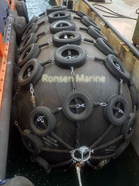
Proper sizing requires calculating the Guaranteed Energy Absorption (GEA). A simplified selection guide based on vessel displacement is as follows:
Vessel Tonnage (DWT) Recommended Size (Diameter x Length)
500 – 1,000 tons 1.0m x 1.5m to 1.2m x 2.0m
1,000 – 5,000 tons 1.5m x 3.0m to 2.0m x 3.5m
10,000 – 50,000 tons 2.5m x 4.0m to 3.0m x 5.0m
80,000+ tons (VLCC/LNG) 3.3m x 6.5m or larger
6. Maintenance and Safety Protocols
To maximize the ROI of your floating fenders, adhere to these maintenance best practices:
Pressure Monitoring: Regularly check internal pressure with a calibrated gauge. Deviations of more than 10% from the initial setting indicate a leak.
Visual Inspections: Every 3 to 6 months, inspect the outer rubber for deep cuts, the chain net for rust, and the safety valve for blockages.
Cleaning: Rinse fenders with fresh water after prolonged exposure to saltwater to prevent salt crystallization and rubber degradation.
Storage: When not in use, store fenders in a cool, shaded area. Deflate them to approximately 20-30% of their working pressure to relieve stress on the rubber layers.

