
Quick Answer: What Are Pneumatic Rubber Fenders?
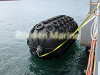
A pneumatic rubber fender—often called a Yokohama fender—is a floating, cylindrical marine fender inflated with compressed air that acts as a shock absorber between two vessels (STS) or between a vessel and a dock (STD). Its reinforced-rubber body compresses under impact, using air compression to absorb berthing energy while keeping reaction force and hull pressure extremely low. Pneumatic fenders are the global standard for ship-to-ship transfers, LNG berthing, and offshore platforms because they automatically follow tidal changes and vessel movement.
Table of Contents
- How Pneumatic Rubber Fenders Work (The Air-Spring Principle)
- Internal Structure: 4 Engineered Layers
 Key Advantages Over Solid & Foam Fenders
- P50 vs P80: Which Initial Pressure Rating to Choose
- Types: Net Type vs Sling Type vs Hydro-Pneumatic
- Standard Sizes & ISO 17357-1:2014 Performance Tables
- Pneumatic vs Foam-Filled vs Cell Fender Comparison
- How to Select the Right Pneumatic Fender
- Installation, Inflation & Maintenance Best Practices
- Service Life & Storage Guidelines
- FAQ: People Also Ask
- Conclusion & Next Steps
1. How Pneumatic Rubber Fenders Work (The Air-Spring Principle) {#how-pneumatic-rubber-fenders-work}
The working principle is based on air compression. When a vessel makes contact:
- The fender’s rubber body deforms and internal air pressure rises.
- Kinetic energy from the vessel is absorbed gradually as the air compresses.
- Reaction force stays relatively low and stable thanks to the “air spring” effect.
- At 60% deflection (the ISO 17357 standard test point), energy absorption peaks while hull pressure remains within safe limits.
- Once the load is removed, the air expands and the fender returns to its original shape.
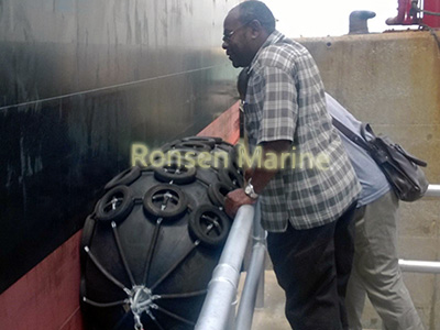
Because they float on the water surface, pneumatic fenders automatically adjust to tidal changes and vessel roll/pitch—something fixed fenders like cell or cone fenders cannot do.
2. Internal Structure: 4 Engineered Layers {#internal-structure}
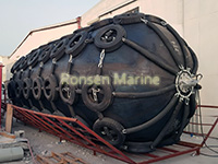
A high-quality pneumatic fender is not just a rubber balloon—it’s a precision-engineered laminate:
LayerMaterialFunctionOuter RubberAbrasion-resistant natural/synthetic rubber compoundProtects inner layers from UV, seawater, impact, and chafingCord Fabric LayerSynthetic tire-cord fabric (nylon/polyester) wound at precise anglesProvides tensile strength; prevents bursting under pressureInner RubberAirtight, low-permeability rubberSeals compressed air inside; prevents leakageEnd Flanges & FittingsGalvanized or stainless steel with air/safety valvesAllows inflation/deflation and secure lifting/anchoring
Most reputable fenders comply with ISO 17357-1:2014 and carry third-party certification (BV, ABS, CCS, DNV, LR).
3. Key Advantages Over Solid & Foam Fenders {#key-advantages}
✅ Extremely low hull pressure – Typically under 25 kN/m², safe for LNG, chemical, and coated hulls.
✅ High energy absorption with low reaction force – Ideal for sensitive vessels and lightweight berthing structures.
✅ Floating & tide-adaptive – Automatically follows tidal swings and vessel movement.
✅ Large contact area – Conforms to curved or irregular hull shapes, spreading impact evenly.
✅ Easy to deploy & relocate – Can be moved between berths or vessels as needed.
✅ Proven for STS operations – The industry standard for ship-to-ship cargo transfer and offshore lightering.
4.  P50 vs P80: Which Initial Pressure Rating to Choose {#p50-vs-p80}
Pneumatic fenders come in two standard initial internal pressures per ISO 17357-1:2014:
ParameterP50 (50 kPa)P80 (80 kPa)Energy absorptionBaseline (ISO GEA)~20–30% higher than P50 at same sizeReaction forceLowerHigherHull pressureLower – ideal for sensitive hullsHigher – check hull limitsFender size for same EALarger diameter neededSmaller diameter possibleBest use casesSheltered berths, STS, general cargoOffshore STS, VLCC/LNG, tight spacesMaintenanceEasier, more forgivingStricter – needs regular pressure checks
Pneumatic Rubber Fender — Layer Structure
4 Engineered Layers · ISO 17357 Compliant</p >
| Layer | Material | Function |
|---|---|---|
| 1Outer Rubber Protective Layer |
Abrasion-resistant natural/synthetic rubber compoundRubber Compound | Protects inner layers from UV, seawater, impact, and chafing |
| 2Cord Fabric Layer Reinforcement Layer |
Synthetic tire-cord fabric (nylon/polyester) wound at precise anglesTire-Cord Fabric | Provides tensile strength; prevents bursting under pressure |
| 3Inner Rubber Airtight Seal Layer |
Airtight, low-permeability rubberSealant Rubber | Seals compressed air inside; prevents leakage |
| 4End Flanges & Fittings Hardware Layer |
Galvanized or stainless steel with air/safety valvesSteel + Valves | Allows inflation/deflation and secure lifting/anchoring |
Engineering Note: All four layers work as an integrated system. Failure in any single layer compromises the entire fender’s performance and safety. Compliant with ISO 17357-1:2014; third-party certifications available (BV, ABS, CCS, DNV, LR).</p >
Rule of thumb: Choose P50 if hull pressure is your constraint (LNG, aluminum, yacht, naval). Choose P80 if you’re tight on space and need maximum absorption per fender—but verify your hull/dock can take the extra reaction force.
⚠️ Never overinflate a P50 fender to 80 kPa. The reinforcement layers and safety factors are different between the two designs.
5. Types: Net Type vs Sling Type vs Hydro-Pneumatic {#types-of-pneumatic-fenders}
🔹 Chain-Tire Net (CTN) Type
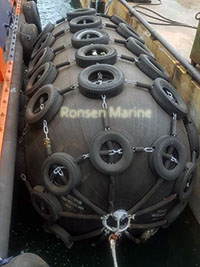
Protective net of chains and used aircraft tires. Extremely durable for heavy STS and rough environments. Downside: tires can scuff delicate hull paint.
🔹 Sling Type
Heavy-duty nylon straps instead of chains/tires. Gentler on hull coating—preferred for yachts, navy vessels, and LNG where surface finish matters.
🔹 Rope Net Type
Rope protection net offering a balance between weight and durability. Often used for mid-sized vessels.
 🔹 Hydro-Pneumatic Type
Partially submerged, designed for submarines and vessels with very low freeboard. Not covered by ISO 17357-1 (falls under separate specifications).
6. Standard Sizes & ISO 17357-1:2014 Performance Tables {#standard-sizes}
Common ISO 17357 pneumatic fender sizes:
📊 ISO 17357-1:2014 Performance Table
Pneumatic Rubber Fender · Guaranteed Energy Absorption & Reaction Force at 60% Deflection 🌐 ISO 17357-1:2014 Compliant
| Nominal Size (Ø × L, mm) |
P50 (50 kPa) | P80 (80 kPa) | ||
|---|---|---|---|---|
| GEA (kJ) | R (kN) | GEA (kJ) | R (kN) | |
| 500 × 1000 | 6 | 64 | 8 | 85 |
| 1000 × 1500 | 32 | 182 | 45 | 239 |
| 1000 × 2000 | 45 | 257 | 63 | 338 |
| 2000 × 3500 | 308 | 875 | 430 | 1,150 |
| 2500 × 4000 | 663 | 1,381 | 925 | 1,815 |
| 3300 × 6500 | 1,814 | 3,015 | 2,532 | 3,961 |
| 4500 × 9000 | 4,755 | 5,988 | 6,633 | 7,551 |
GEA = Guaranteed Energy Absorption (kJ) · R = Reaction Force (kN) · All values measured at 60% deflection per ISO 17357-1:2014.
P50 fenders operate at 50 kPa initial internal pressure; P80 fenders at 80 kPa. Never overinflate a P50 fender to 80 kPa — the reinforcement design differs between the two.
P50 — Standard Pressure (50 kPa)
P80 — High Pressure (80 kPa)
All values at 60% deflection per ISO 17357-1:2014. GEA = Guaranteed Energy Absorption; R = Reaction Force.
💡 Sizing insight: A Ø3.3m × L6.5m P80 fender absorbs ~2,532 kJ at 60% deflection—enough for VLCC-to-VLCC side-by-side transfer. Always verify with manufacturer performance curves, not just dimensional tables.
7. Pneumatic vs Foam-Filled vs Cell Fender Comparison {#comparison-table}
Source synthesis from industry references.
8. How to Select the Right Pneumatic Fender {#selection-guide}
Step 1: Calculate Berthing Energy (E)
Use the PIANC methodology:
E = \frac{1}{2} M_e V^2 C_e C_m C_s C_c
Where:
- M_e = Effective displacement (vessel mass + added mass of water)
- V = Approach velocity (typical 0.10–0.30 m/s for large vessels under tug assist)
- C_e, C_m, C_s, C_c = Eccentricity, virtual mass, softness, and berth configuration coefficients
Step 2: Define Constraints
- Allowable hull pressure (check classification society rules)
- Berth structure reaction-force limit
- Tidal range and dolphin height
- Environmental exposure (waves, currents, temperature)
Step 3: Match to Performance Curve
Select fender size so that absorbed energy ≤ GEA at 60% deflection, with reaction force ≤ hull/structure limits.
Step 4: Choose Type & Accessories
- STS heavy duty → CTN type, P80
- Yacht/naval → Sling type, P50
- Submarine → Hydro-pneumatic
⚠️ Common mistake: Specifying based on dimensional size alone. Two fenders with the same Ø×L can have vastly different energy absorption if pressure ratings differ. Always use ISO performance tables.
9. Installation, Inflation & Maintenance Best Practices {#installation-maintenance}
Pre-Deployment Checklist:
✅ Inflate with clean, dry air or nitrogen to rated initial pressure
✅ Verify safety relief valve functions correctly
✅ Inspect chain/tire net or sling for corrosion, wear, or loose connections
✅ Confirm end-flange bolts and shackles are tightened to spec
Routine Maintenance:
- Pressure checks: Monthly or before each operation. Temperature changes affect pressure—hot sun can raise pressure 10–15%.
- Visual inspection: Check for cuts >1 cm deep, exposed cord fabric, valve leakage, or tire-net wear.
- Cleaning: Rinse with fresh water after heavy fouling to remove salt/silt.
- Valve service: Replace valve cores every 6 months in high-use environments.
Storage (when not in use):
- Deflate partially or fully
- Store in cool, dry, well-ventilated area away from direct sunlight and ozone sources (electric motors, welding equipment)
- Keep away from sharp objects and chemicals
10. Service Life & Storage Guidelines {#service-life}
With proper maintenance, a high-quality pneumatic fender typically lasts 10–15 years. Factors affecting lifespan:
✅ Keeping internal pressure within ±5% of rated
✅ Rinsing after heavy fouling
✅ Storing deflated + shaded when idle
✅ Inspecting tire-nets/chains for corrosion
Replace immediately if:
- Cuts expose cord fabric
- Air leakage cannot be stopped by valve service
- Permanent deformation exceeds manufacturer tolerance
11. FAQ: People Also Ask {#faq}
Q: Are pneumatic fenders the same as Yokohama fenders?
A: Yes. “Yokohama fender” is the industry tradename, named after The Yokohama Rubber Co., which pioneered them. Technically they are floating pneumatic rubber fenders.
Q: Are pneumatic fenders ISO certified?
A: Reputable manufacturers produce to ISO 17357-1:2014 (high-pressure) or ISO 17357-2 (low-pressure). Always request third-party certs (BV, ABS, CCS, DNV, LR).
Q: Can pneumatic fenders be used on a fixed dock instead of cone fenders?
A: They can, but usually shouldn’t if the berth is permanent and high-traffic. Pneumatics cost more to maintain (air checks, net wear) and can drift if not properly tensioned. Fixed docks typically do better with Super Cone or cell fenders, reserving pneumatics for STS or extreme tidal cases.
Q: What’s the difference between pneumatic fenders and marine airbags?
A: They are not interchangeable. Marine airbags are for ship launching and salvage (pure buoyancy + rolling). Pneumatic fenders are certified berthing devices with ISO performance tables. Different tool, different job.
Q: How often should I inspect pneumatic fenders?
A: At least quarterly, or after any major impact or severe weather event. High-traffic terminals may require monthly checks.
Q: Can I repair a punctured pneumatic fender?
A: Small cuts can be patched with cold-cure rubber patches. Large damage or cord exposure requires professional factory repair or replacement.
12. Conclusion & Next Steps {#conclusion}
Pneumatic rubber fenders remain the gold standard for floating, low-reaction-force marine protection—especially for ship-to-ship transfers, LNG terminals, and offshore platforms where fixed fenders cannot adapt to tidal and vessel movement. Selecting the right combination of size, pressure rating (P50/P80), and protection type (CTN/Sling/Hydro) requires matching berthing energy calculations to ISO 17357 performance curves—not guesswork.
Need Help Sizing Your Pneumatic Fender System?
Our marine engineering team can calculate berthing energy for your specific vessel class, recommend optimal Ø×L and pressure rating, and provide ISO 17357-compliant drawings and performance curves.
👉 Download our Pneumatic Fender Sizing Worksheet
👉 Request a free technical proposal and quotation

