News

  • 01 Aug

    What Is a Cone Rubber Fender? The Ultimate Guide for Marine Engineers (2026)

    Quick Answer: What Is a Cone Rubber Fender?

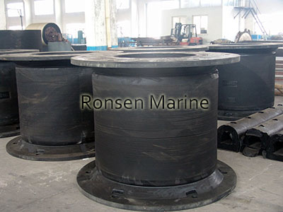
    A cone rubber fender is a high-performance marine fender with a conical shape that absorbs massive berthing impact energy while exerting low reaction force on both the vessel hull and the dock structure. Its unique truncated-cone geometry allows it to deflect up to 70% of its height, making it one of the most efficient fenders for large container ships, oil tankers, and LNG carriers at high-traffic ports.

    How Does a Cone Rubber Fender Work?

    When a vessel approaches a berth, the cone fender compresses axially and flexes radially. Its conical profile allows it to:

    • Absorb high impact energy by deflecting up to ~70% of its height without a sharp rise in reaction force.
    • Self-center under load, staying aligned even during oblique berthing angles (up to 10–15° off-axis).
    • Distribute loads evenly when paired with a steel frontal panel and UHMW-PE facing pad, reducing hull pressure and preventing marks.
    • Resist shear and torsion, making it ideal for locations with strong currents, tides, or frequent vessel movement.

    Most cone fenders are single-piece moldings made from marine-grade, UV- and seawater-resistant rubber compounds, often installed with pre-built-in bolts, chains, and frontal panels.

    Key Advantages of Cone Rubber Fenders

    Compared with traditional arch or cylindrical fenders, cone fenders offer several performance benefits:

    ✅ Highest energy absorption per unit size – smaller cones can replace larger cell or arch fenders, lowering project cost.

    ✅ Low reaction force – gentler on both quay walls and ship hulls.

    ✅ Excellent shear resistance – stable under oblique impacts and tidal movement.

    ✅ Long service life – marine-grade rubber compounds resist UV, ozone, and salt corrosion.

    ✅ Low maintenance – robust one-piece molding with minimal moving parts.

    ✅ Flexible installation – can be mounted normally or reversed on narrow structures.

    Typical Applications
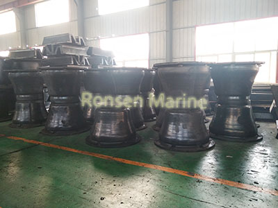
    Cone rubber fenders are widely used in medium- to high-traffic terminals handling large vessels, including:

    • Container terminals and general cargo wharves
    • Oil, gas, and LNG berths
    • RoRo (roll-on/roll-off) and cruise terminals
    • Naval and offshore platform dolphins
    • Ports with large tidal ranges or frequent berthing cycles

    Cone Fender vs. Cell Fender: What’s the Difference?

    FeatureCone Rubber FenderCell Rubber FenderEnergy absorptionHigher (up to 70% deflection)Moderate (~52.5% deflection)Reaction forceLower at same energy levelHigherShear resistanceExcellent (conical geometry)GoodFrontal panel compatibilityOptimized for large panelsCompatibleSpace requirementCompact footprintSimilar

    Bottom line: If your priority is maximizing energy absorption while keeping reaction force low—especially with large panels or angled berthing—cone fenders are typically the better choice.

    Common Cone Fender Sizes & Customization

    Standard cone fenders range from roughly 300 mm to 1,500+ mm in height, with corresponding reaction-force and energy-absorption ratings tailored to specific berthing energies. Many suppliers offer:

    • Custom heights and diameters
    • Different rubber hardness grades (standard / intermediate / high-energy compounds)
    • Custom colors and mounting hardware
    • Pre-assembled kits with frontal panels, UHMW-PE pads, chains, and anchor bolts

    Always specify your vessel size, berthing angle, tidal range, and design energy when requesting a quotation.

    Maintenance, Inspection, and Longevity Practices

    Routine Inspection Checklists for Marine Operators

    Port authorities should establish a scheduled maintenance program to inspect their fendering assets at least once every six months. A standard inspection checklist should include:

    • Checking the rubber cone body for deep cuts, ozone cracking, or permanent deformation.
    • Inspecting all anchor bolts and chain shackles for signs of severe marine corrosion or loosening.
    • Measuring the remaining thickness of the UHMW-PE face pads to ensure they have not worn down to the steel panel bolts.
    • Verifying that weight support and tension chains maintain the correct amount of slack.

    Troubleshooting Common Wear Issues (Friction, Shear, and UV Damage)

    If an operator notices localized cracking near the base of the cone, it often indicates excessive shear stress caused by a broken tension chain. Accelerated wear on the UHMW-PE pads suggests high amounts of silt or rough hull surfaces scraping the berth. Replacing worn face pads early prevents metal-on-metal contact, preserving both the vessel hull and the internal steel frame from costly damage.

    Estimating and Extending the Service Life of a Cone Fender

    A premium, properly maintained cone fender system can easily achieve an operational lifespan exceeding 20 years. To maximize longevity, port operators should keep marine growth cleared from around the rubber base and ensure that chain assemblies remain properly adjusted. Investing in high-quality UV-stabilized rubber compounds during the initial procurement phase pays massive dividends by preventing premature environmental degradation.

    FAQ: Cone Rubber Fenders

    Q: What vessels are cone rubber fenders suitable for?

    A: They’re commonly used for container ships, bulk carriers, oil/LNG tankers, cruise ships, and naval vessels at medium-to-largeQ: How long does a cone fender last?

    A: With proper installation and occasional inspection, high-quality marine-grade cone fenders typically last 10–15+ years in harsh saltwater environments.

    Q: Do cone fenders require a frontal panel?

    A: While not strictly mandatory, most installations include a steel frontal panel with a UHMW-PE facing pad to spread hull pressure and reduce friction.

    Q: Can cone fenders be used on narrow jetties?

    A: Yes—cone fenders can be mounted in reverse (small face toward the quay) to fit structures with limited footprint.

    Q: Are cone fenders compliant with international standards?

    A: Reputable manufacturers produce cone fenders in accordance with standards such as PIANC Guidelines and ISO 17357.

    Conclusion

    A cone rubber fender is one of the most efficient, durable, and versatile solutions for protecting docks and vessels during berthing. Its conical geometry delivers industry-leading energy absorption with low reaction force, excellent shear resistance, and long-term reliability—making it a smart investment for modern port infrastructure.

    Need a Quote or Technical Proposal?

    If you’re planning a new terminal or upgrading an existing berth, our engineering team can help you select the right cone fender size, compound, and mounting system for your design energy and tidal conditions.

    👉 Contact us today for a free technical proposal and customized quotation.

    By Ronsen Marine Uncategorized
  • 28 Jul

    What Is Ship Launching Airbag? The Ultimate Guide to Marine Airbags

    Traditionally, building a new vessel meant constructing massive concrete slipways—a process that was expensive, time-consuming, and environmentally invasive. Today, shipyards around the world are adopting a revolutionary alternative: the ship launching airbag. But what exactly is a ship launching airbag, and why has it become the gold standard for modern shipbuilding?
    This guide explains the construction, working principles, and key advantages of marine rubber airbags, also known as “Yokohama-type launching airbags.”

    What Is a Ship Launching Airbag?

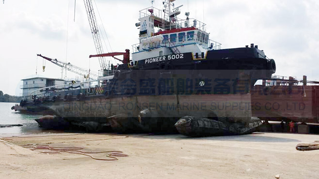
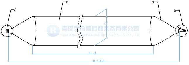
    A ship launching airbag is a large, cylindrical, inflatable device made from reinforced synthetic-tire-cord rubber. It is designed to lift a vessel off its support blocks and roll it safely into the water. Unlike rigid slipways, these airbags act as flexible rollers, adapting to the hull shape and distributing the vessel’s weight evenly across the ground.

    They are primarily used for:

    • Ship Launching: Moving newly built vessels from land to water.
    • Ship Landing/Docking: Pulling vessels ashore for repair without a dry dock.
    •  
    • Heavy Object Moving: Transporting heavy structures like bridges, caissons, and large tanks.
    The Core Construction: Multi-Layer Technology

    The durability of a ship launching airbag comes from its sophisticated multi-layer design. High-quality airbags, compliant with the ISO 14409 standard, typically consist of three main sections:

    1. Inner Rubber Layer (Airtight Seal)

    This inner layer maintains air tightness. It is made from high-quality natural rubber that remains flexible and impermeable under pressure. Its primary job is to prevent air leakage and protect the internal reinforcement layers from moisture.

    2. Synthetic-Tire-Cord Reinforcement Layer

    This is the backbone of the airbag. Multiple layers (typically 4 to 12 layers) of high-tensile synthetic tire cord fabric are wound around the core at specific angles (usually 54°44′ ± 2°). This crisscross pattern provides exceptional tensile strength and explosion-proof capabilities, allowing the airbag to withstand pressures exceeding 250 kPa.

    3. Outer Rubber Layer (Protective Skin)

    The outermost layer protects the internal structure from external damage. It is formulated to resist abrasion, aging, UV radiation, and acid/alkali corrosion. The thickness of this layer is critical—it determines how well the airbag can withstand friction against the ground and the ship’s hull during rolling.

    Cross-section diagram of a ship launching airbag showing inner rubber, synthetic tire cord layers, and outer protective skin

    Figure 1: Cross-section of a typical ship launching airbag structure.

    How Do Ship Launching Airbags Work?

    The physics behind airbag launching is straightforward but ingenious:

    1. Placement: Deflated airbags are placed beneath the vessel’s keel, perpendicular to the hull.
    2. Inflation: Airbags are inflated to a predetermined pressure (typically 0.05–0.15 MPa), lifting the vessel off its wooden support blocks.
    3. Removal of Blocks: Once the hull is fully supported by the airbags, the wooden blocks are removed.
    4. Launching: Using winches or gravity, the vessel begins to move. As the ship rolls forward, the airbags rotate, acting like a conveyor belt of giant rollers, smoothly transferring the vessel into the water.

    Key Specifications and Standards

    When sourcing airbags, it is crucial to understand the technical specifications. The international benchmark is ISO 14409:2011 (Ships and marine technology — Ship launching air bags).

    Parameter Typical Range Notes
    Diameter (D) 0.8m – 2.5m Larger diameters distribute pressure better.
    Effective Length (EL) 6.0m – 22.0m Determines the total load-bearing area.
    Layers (N) 4 – 12 plies More layers = higher safety factor & pressure rating.
    Safety Factor ≥ 4:1 Bursting pressure vs. working pressure.

    Advantages Over Traditional Slipways

    Why have thousands of shipyards switched to airbag technology?

    • Cost-Effective: Eliminates the need for expensive civil engineering (concrete ramps).
    • Space Saving: Allows launching in locations with limited infrastructure.
    • Versatility: Suitable for various vessel types, from small fishing boats to 100,000 DWT tankers.
    • Environmentally Friendly: Reduces concrete usage and ground disturbance.
    • Flexibility: Airbags can be deflated and moved easily, allowing for quick setup and takedown.

    Maintenance and Storage Best Practices

    To ensure a long service life (typically 6–8 years), proper maintenance is essential:

    • Cleaning: Rinse with fresh water after use, especially if used in saltwater or muddy areas.
    • Drying: Ensure the airbag is completely dry before storage to prevent mildew.
    • Powdering: Apply talcum powder to the outer surface to prevent the rubber layers from sticking together.
    • Storage: Store indoors in a cool, dry, and dark place, away from acids, alkalis, and sharp objects.

    Frequently Asked Questions (FAQ)

    Q: How much weight can a ship launching airbag support?

    A: The load capacity depends on the diameter, length, and number of reinforcing layers. A standard 1.5m x 12m airbag with 6 layers can typically support approximately 100–150 tons per linear meter under safe working pressure.

    Q: Are ship launching airbags safe?

    A: Yes, when used correctly and manufactured to ISO 14409 standards. The multi-layer synthetic-tire-cord construction provides a high safety factor (usually 4:1 or higher), making catastrophic failure extremely rare.

    Q: Can airbags be used for landing ships (hauling out)?

    A: Absolutely. The process is essentially the reverse of launching. Airbags are placed under the hull, inflated to lift the vessel, and then used to roll the ship onto land for repairs or maintenance.

    Q: What is the difference between launching airbags and salvage airbags?

    A: While similar in construction, salvage airbags are often designed with higher buoyancy-to-weight ratios and specific connection points for underwater lifting operations, whereas launching airbags are optimized for rolling friction and ground contact.

    Conclusion

    The ship launching airbag is more than just an inflatable bag; it is a sophisticated piece of marine engineering that has democratized shipbuilding. By offering a safe, economical, and flexible alternative to traditional slipways, it allows shipyards of all sizes to operate efficiently.

    Looking for ISO 14409 certified ship launching airbags? Ronsen Marine supplies high-performance marine airbags with DNV-GL, ABS, and CCS certifications. Contact our technical team</a > today for a customized calculation report and competitive pricing


    Related Reading: Ship Launching Airbags Pneumatic Rubber Fenders How to Install Ship Launching Airbags Safely

    By Ronsen Marine Uncategorized
  • 28 Jul

    Support Buoys

    Support Buoys: The Complete Guide to Offshore Mooring Buoys

    In offshore marine operations, reliability is everything. From Single Point Mooring (SPM) systems to subsea cable installations, support buoys provide the critical buoyancy needed to keep chains, hoses, and cables safely afloat. Choosing the wrong buoy can lead to equipment loss, downtime, and safety hazards.
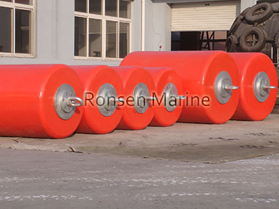
    This guide explains what support buoys are, how they are constructed, the main types available, and how to select the right one for your offshore project.

    What Are Support Buoys?

    Support buoys are heavy-duty floating devices designed to support and protect marine infrastructure—primarily mooring chains, ropes, and hoses. Unlike small navigational markers, offshore support buoys must withstand high tensile loads, continuous wave action, UV exposure, and corrosive seawater.

    Modern foam-filled support buoys are virtually unsinkable, making them the preferred choice for mission-critical offshore applications.

    Support Buoy Construction: Why Foam-Filled Wins

    Premium marine support buoys, such as those manufactured by Ronsen Marine, use a three-layer closed-molding process:

    1. Core: Closed-Cell EVA/PE Foam

    The core consists of low-density polyethylene (PE) or Ethylene-Vinyl Acetate (EVA) foam. Its closed-cell structure ensures 100% watertight integrity—even if the outer skin is punctured, the buoy retains full buoyancy.

    2. Reinforcement: Nylon Tire Cord Layers
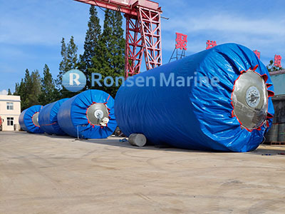
    Multiple layers of high-tenacity nylon tire cord fabric wrap the core, absorbing tensile stress from chains and preventing elongation under dynamic loads.

    3. Outer Skin: Polyurethane Elastomer

    The outer shell is a thick, seamless polyurethane (PU) elastomer coating that is:

    • Abrasion-resistant – withstands friction from chains and hulls.
    • UV-stable – prevents chalking and surface degradation.
    • Non-marking – optional colored PU avoids hull staining.

    Types of Support Buoys

    Selecting the correct type depends on your specific offshore application:

    A. Chain-Through Support Buoys (Cylindrical)

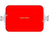
    These buoys feature a steel central tube, allowing the mooring chain to pass directly through the buoy.

    • Application: Used as chain-stopper buoys in SPM systems to support chain weight and reduce hawse-pipe tension.
    • Advantage: Excellent load distribution and stability in strong currents.

    B. Pick-Up Buoys (Cylindrical or Spherical)

    Smaller, lightweight buoys attached to mooring lines via pick-up ropes or chain plates.

    • Application: Retrieving submerged mooring lines, marking subsea assets, and providing auxiliary floatation.
    • Advantage: Easy handling and rapid deployment.

    C. Foam-Filled Support Buoys (General Purpose)

    Versatile buoys used across dredging, offshore wind, and cable-lay operations.

    • Application: Supporting suction hoses, marker buoys for turbines, and temporary mooring points.
    • Advantage: Unsinkable design and minimal maintenance.

    Key Applications of Offshore Support Buoys

    • Oil & Gas (SPM Systems): Mid-line chain support and tension reduction.
    • Subsea Cable Installation: Keeping power and fiber-optic cables afloat during lay operations.
    • Offshore Wind Farms: Marking turbine locations and guiding SOVs.
    • Dredging Operations: Supporting discharge pipes and suction hoses.
    • Defense & Ports: Temporary moorings and security barriers.

    How to Select the Right Support Buoy

    Follow these steps to specify the correct buoy:

    1. Calculate Required Buoyancy: Determine the submerged weight of the chain/rope plus desired freeboard.
    2. Match Chain Size: Ensure the central tube diameter fits your chain (e.g., 64mm, 76mm, 84mm).
    3. Assess Environmental Conditions: Factor in tidal range, current velocity, and wave height.
    4. Confirm Compliance: Verify alignment with PIANC guidelines and OCIMF recommendations.
    5. Choose Materials: Specify hot-dip galvanized or epoxy-coated steelwork for maximum corrosion resistance.

    Support Buoys vs. Marine Fenders: What’s the Difference?

    Although both float, their roles differ significantly:

    • Support Buoys: Provide flotation and tension relief for mooring lines and chains.
    • Marine Fenders: Absorb kinetic energy during vessel berthing to protect hulls and structures.

    For comprehensive protection, offshore projects often deploy both foam-filled support buoys and foam-filled marine fenders

    Maintenance Tips for Long-Term Performance

    • Inspect PU skins annually for deep cuts or abrasions.
    • Rinse buoys with fresh water after deployment in polluted or tropical waters.
    • Check galvanized steelwork for signs of corrosion every 12 months.
    • Store spare buoys in shaded, ventilated areas when not in use.

    Frequently Asked Questions (FAQ)

    Q: How long do foam-filled support buoys last?

    A: With proper inspection and care, high-quality foam-filled support buoys typically deliver 10–15 years of service life, thanks to UV-stable polyurethane skins.

    Q: Are support buoys truly unsinkable?

    A: Yes—when constructed with closed-cell EVA/PE foam cores. Unlike air-filled buoys, foam cores displace water permanently and remain afloat even after major skin damage.

    Q: Can support buoys be customized?

    A: Absolutely. Ronsen Marine offers customization in diameter, length, color (yellow, orange, red, green), and hardware (galvanized vs. stainless steel).

    Conclusion

    Investing in the right support buoys enhances safety, reduces downtime, and lowers lifecycle costs. Foam-filled, polyurethane-skinned buoys deliver unmatched reliability in the harshest offshore environments.

    Need support buoys for your next offshore project?
    Ronsen Marine supplies ISO-certified foam-filled support buoys worldwide. Contact our engineering team</a > today for technical drawings and a competitive quotation.


    Related Resources:
    Cylindrical Chain Support Foam Buoys
    Foam Filled Fenders
    What Is a Foam Filled Fender?

    By Ronsen Marine Uncategorized
  • 25 Jul

    What Is a Foam Filled Fender?

    Foam Filled Fenders

    Foam Filled Fender is a fender that features a polyurethane elastomer outer layer, a nylon fiber reinforcement layer, and a foam solid core layer serving as the filling layer, ensuring high buoyancy and zero water absorption.

    What’s the constructure of a foam filled fender?

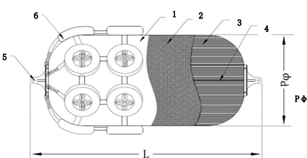
    The fender consists of an outer layer of polyurethane elastomer, a nylon fiber reinforcement layer, and a foam core. The schematic diagram of the fender structure is shown below.

    Foam Filled Fender

    1. Outer polyurethane elastomer layer;
    2——Nylon fiber reinforcement layer;
    3——Foam solid core layer;
    4. Support inner pipe (optional);
    5—Flange structure;
    6——Tire guard (optional).
    L——Fender length, unit in millimeters (mm);
    Pφ —— Fender diameter, unit in millimeters (mm)

    What’s the classification?

    Foam Fenders can be divided into:a) Z-type – heavy-duty fender with high reaction force and high energy absorption under the same compression conditions.
    b) Q-type – lightweight fender with low reaction force and low energy absorption under the same compression conditions.
    What’s appearance quality?

    The surface of the fender should have a uniform texture and should not have defects such as foreign objects, bubbles, cracks, etc. that affect its performance.
    The filling material inside the fender should not be exposed.

    What’s the material?

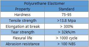
    The physical properties of polyurethane layer elastomer materials shall comply with the provisions of Table 4.

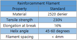
    The nylon fiber reinforcement layer material can use 1400D2/V1 nylon, and its physical properties should comply with the specifications in Table 5.

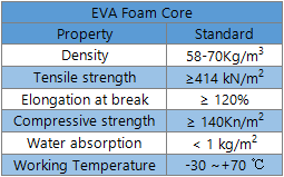
    The physical properties of foam solid core material shall comply with the provisions in Table 6.


    hat’s the fender body tests?

    Appearance quality: Visual inspection is used for inspection

    Specifications and Dimensions: Use steel tape, steel ruler, and vernier caliper that meet the accuracy requirements for inspection

    Dimensional tolerance: Use steel tape, steel ruler, and vernier caliper that meet the accuracy requirements for inspection

    Mechanical Properties: Perform testing and calculation according to the method specified in Appendix A

    What’s the material test?
    The physical properties of polyurethane layer elastomer materials shall be determined in accordance with the relevant standards specified in Table 4.
    The physical properties of nylon fiber reinforced layer materials shall be determined in accordance with the relevant standards specified in Table 5.
    The physical properties of foam solid core material shall be determined according to the relevant standards in Table 6.

    What’s the type test?

    Timing of Inspection
    Type inspection should be conducted for fenders in any of the following situations:
    a) The first production product for trial production, finalization identification, and factory transfer production of new products;
    b) When there are significant changes in structure, materials, and processes that can affect product performance;
    c) When the product is discontinued for more than 6 months and production resumes;
    d) When the higher-level testing agency requires type inspection.

    What’s the transportation?

    Fenders should be kept clean during transportation.
    Prevent fenders from being dropped, bumped, dragged, or rolled.
    Prevent fenders from being hooked, suspended, pricked, or scratched by hard objects.
    Prevent the fender from coming into contact with substances such as acids, alkalis, oils, and organic solvents.

    What’s the storage?

    Fenders should be stored indoors at a temperature of -10 ℃ to 30 ℃, avoiding direct sunlight and exposure to rain and snow.
    Prevent the fender from coming into contact with substances such as acids, alkalis, oils, and organic solvents.
    The fender should be at least 1 meter away from the heat source.


    W

    By Ronsen Marine Uncategorized
  • 23 Jul

    What Is Support Buoy?

    Support Buoys

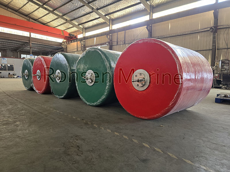
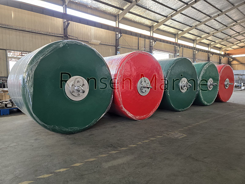
    Support buoys are produced from closed cell EVA/PE resilient foam, sprayed with self-colored polyurethane elastomer skin, are a kind of general surface support buoys for offshore mooring buoys system. They are widely used as the warning buoys for ships, vessels, barges and boats as well as marines docking & berthing. Support Buoys are normally classified into pick up buoys, chain through buoys, cylindrical buoys, anchor pendant buoys and mooring buoys etc.

    Support Buoys Construction

    • Closed cell resilient foam core, unsinkable design

    Cylindrical chain support foam buoys are manufactured with high density closed-cell PE/EVA resilient foam core. This resilient foam ensure buoys self fendering with high impact absorption capacity, even the polyurethane elastomer skin punctured, cylindrical chain support foam buoys will be unsinkable without absorbing any water.

    • Tough reinforced Nylon Layer
    Support Mooring Buoys

    Each cylindrical chain support foam buoy is constructed of polyurethane elastomer reinforced with nylon filament layer. The polyurethane skin is unique elastomer especially for offshore & subsea applications. The elastomer skin is high resistance to abrasion, fatigue and ultra violet degradation and significantly much more durable.

    • Excellent end steel works

    There is a central tube encased in the closed-cell urethane foam central body of cylindrical chain support foam buoys. The central tube is either epoxy coated or hot-dipped galvanized, with longitudinal gussets and extend load distribution flanges at each end. Optional accessories like bail eye, clevis eye, swivel, chain locking plate, single locking pin end fitting etc.

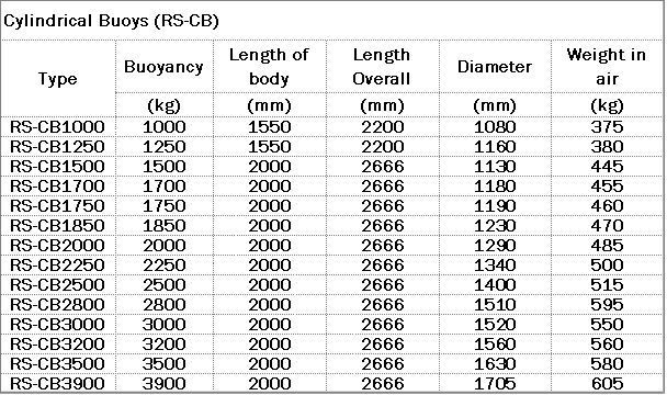
    Cylindrical Chain Support Foam Buoys Specification

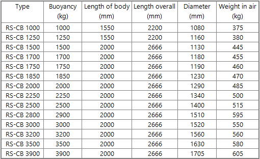
    Cylindrical Buoys (RS-CB)

    Cylindrical Buoys Foam Buoys-RONSEN MARINE


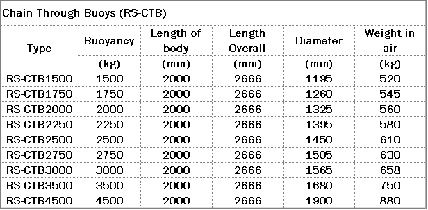
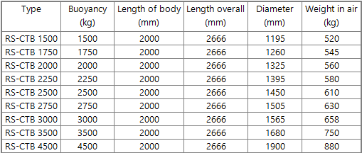
    Chain Through Buoys (RS-CTB)

    Cylindrical Chain Through Buoys CTB - RONSEN MARINE


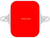
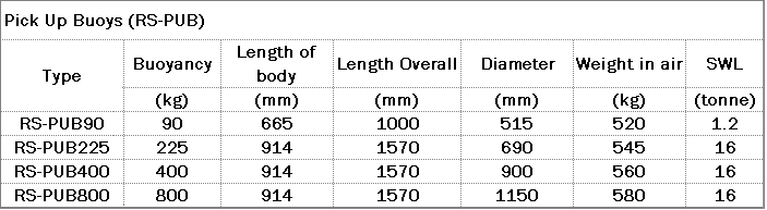
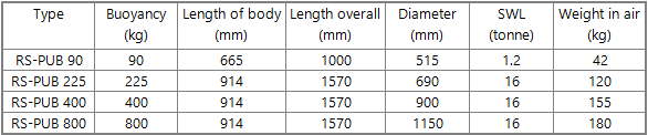
    Pick Up Buoys (RS-PUB)

    Pick Up Buoys Foam Buoys -RONSEN MARINE

    By Ronsen Marine Uncategorized
  • 22 Jul

    What Is Cylindrical Rubber Fender?

    Cylindrical Rubber Fenders

    The cylindrical rubber fender, with its high elasticity rubber material and cylindrical design, efficiently absorbs the impact force of ships, evenly disperses the impact energy, and significantly extends the service life of port facilities. It is an ideal protection choice for ports with large tidal ranges.
    Characteristics and Applications of Cylindrical Rubber Fenders
    The cylindrical rubber fender is an important component of port protection facilities, and its unique structural design enables it to effectively absorb impact energy when ships berth.
    This type of fender is made of highly elastic rubber material, and its cylindrical appearance allows it to evenly distribute ship impact forces, protecting the dock structure and hull from damage. Cylindrical rubber fenders are suitable for small and medium-sized docks and berths, especially performing well in ports with large tidal ranges.
    Its simple structure, economical cost, and convenient installation make it the preferred protection solution for many port projects.
    The most prominent feature of cylindrical rubber fenders is their impact resistance.
    Rubber materials themselves have excellent resilience and energy absorption capacity. When a ship docks, the fender transforms kinetic energy into elastic potential energy through deformation, which is then slowly released to reduce the impact on the dock and the ship.
    This buffering effect greatly reduces the risk of structural damage and extends the service life of port facilities.
    When installing cylindrical rubber fenders, tidal changes and water level fluctuations need to be considered.
    Fenders are usually fixed at the forefront of the dock with bolts, and their installation height needs to be determined according to the local highest and lowest tide levels to ensure that they can function under various water level conditions.
    During the installation process, attention should also be paid to controlling the gap between the fender and the dock structure. If it is too large, it will reduce the protective effect, while if it is too small, it may affect the compression deformation space of the fender.
    In terms of maintenance, cylindrical rubber fenders are relatively simple.
    Regularly inspect the surface for cracks, wear, or aging.
    The rubber material itself is resistant to seawater corrosion, but it will gradually age under long-term ultraviolet irradiation, so surface protection treatment can be carried out if necessary.
    Compared to other types of fenders, cylindrical structures do not have complex internal components and have lower maintenance costs.

    By Ronsen Marine Uncategorized
  • 22 Jul

    Pneumatic Fenders Material

    Pneumatic Fenders

    Pneumatic Fenders is a hollow bag type anti-collision device made of high-strength synthetic rubber and special skeleton materials, which forms a buffering system with specific pressure and elastic modulus by filling compressed air.
    Pneumatic fenders are mainly composed of hollow rubber airbags made of high-strength synthetic rubber and special skeleton materials. Its basic structure includes outer layer adhesive, inner layer adhesive, curtain fabric layer (skeleton material), winding ring, end flange, as well as components such as inflation pipe, deflation valve, one-way valve, etc. The outer layer of adhesive protects the skeleton material and the inner layer of adhesive from external damage; The inner layer of adhesive prevents gas leakage and maintains air pressure; The curtain fabric layer serves as the skeleton material to provide structural strength.
    Referring to the patent “An Pneumatic Rubber Fender Structure” (CN202320874102.0), its structure also includes a buffering anti-collision mechanism and a sealing mechanism. The buffer anti-collision mechanism (such as fixed blocks, connecting ropes, and anti-collision tires) cooperates with the inner sealing plate to enhance the buffering and shock absorption effect; Sealing mechanisms, such as flanges and hemispherical sealing shells, can prevent components such as inflation pipes, deflation valves, and check valves from being corroded by water mist, thereby improving their service life.
    According to the form of external protection, pneumatic rubber fenders can be divided into unsheathed and sheathed types. Sheath type (such as tire chain mesh, rope tire, wire rope tire mesh, etc.) extends the service life of fenders by wrapping a sheath (such as tire rope mesh) outside the bladder.

    Pneumatic Fenders

    Its main features include:
    1. The absorption of impact energy is relatively large, and the anti impact force on the ship is relatively small.
    2. The installation is relatively simple.
    3. It has good elasticity and is less likely to undergo permanent deformation under compression.
    4. Lightweight. This type of fender has been applied in scenarios such as oil tankers, container ships, yachts, offshore platforms, large shipyards, docks, and bridge piers.
    5. The performance is relatively stable under inclined compression conditions.
    Some products are made using integral winding technology, with no seams and uniform force distribution at all points. Their overall performance is better than traditional overlapping fenders.
    This type of product needs to pass relevant quality system certification and classification society inspection.

    By Ronsen Marine Uncategorized
  • 18 Jul

    Marine Airbags Operation Guideline

    I. Scope of Application and Definition

    This specification applies to all operations involving the lifting and gradual launching of ships from above their self-supporting structures using an marine airbag system in shipyards, shipbuilding yards, and related dock areas. The marine airbag system typically consists of multiple marine airbag units, an air supply system, a control valve assembly, pressure gauges and pipelines, support and positioning components, as well as cushioning parts that come into contact with the ship’s hull. The launching operation involves various factors such as mechanical loads, hydrodynamics, and environmental impacts, and must be conducted under the premise of ensuring the safety of the ship’s structure, the personal safety of the operating personnel, and the protection of the surrounding environment.

    II. Basic Principles and Safety Requirements

    With safety as the premise, we adhere to the principle of “who organizes, who is responsible, who operates”, clarifying the responsibilities and authorities of personnel at all levels.
    Conduct a risk assessment before the operation, list key risk points and corresponding countermeasures; assign dedicated safety personnel on site to oversee the implementation.
    The ship launching airbag and pipeline system should comply with the design parameters, and any modifications must be approved by the design unit or manufacturer and documented in writing.
    The operation site should be equipped with necessary risk elimination and emergency evacuation routes, maintain smooth communication, and set up emergency assembly points and rescue equipment when necessary.
    The processes of marine ship launching airbag inflation and deflation, hull lifting, and launching need to be controlled synchronously to avoid single-point overload, eccentric loading, or asymmetric stress.
    Prioritize environmental protection, prevent incidents such as seawater pollution and gas source leakage, and ensure that all actions are carried out within permissible waters and weather conditions.

    III. Organization and Responsibilities Project Supervisor

    Fully responsible for the planning, resource allocation, risk control, and final acceptance of the water balloon operation.
    Operation team leader (on-site person in charge): coordinate on-site, execute according to procedures, and ensure smooth connection between each link.
    Air source and valve control personnel: responsible for connecting the air source system, setting pressure, operating valves, and monitoring safety.
    Safety supervisor: Inspect the site, check the completeness of personal protective equipment, area signage, protective facilities, and emergency equipment, and promptly correct any violations.
    Command signaler: Pass instructions between the equipment control console and the hull, ensuring accurate and error-free transmission of information.
    Observation and recording personnel: Record key data such as the hull’s attitude, marine airbag status, load, and displacement for evaluation and tracking purposes.

    IV. Site Preparation and Materials

    The site should have a clean working area, a level base, stable lifting points, and necessary anti-slip and anti-collision measures.
    The airbag unit, connecting pipeline, pressure relief and exhaust equipment, pressure gauge, valve assembly, control panel, limiting device, damping and buffer components, etc., should be intact and fully inventoried, and should match the ship’s type and weight.
    Safety protective equipment, including helmets, safety shoes, gloves, goggles, etc., should be fully equipped. Emergency rescue tools and firefighting equipment should be readily available and functional on site.
    The weather and sea conditions must meet the launching requirements, with factors such as wind, waves, visibility, and temperature falling within acceptable ranges; if these conditions are not met, the operation should be postponed.

    By Ronsen Marine Uncategorized
  • 11 Jul

    What Is Cylindrical Rubber Fenders?

    Cylindrical Fenders

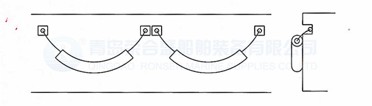
    Cylindrical rubber fenders perform better during longitudinal and crosswise motion when ship berthing. Cylindrical marine rubber fenders are one rubber marine fenders in hollow cylindrical shape, they can be used together with arch rubber fenders, or d type rubber fenders. Cylindrical rubber fender are easier to be installed, either horizontally, vertically or diagonally by anchoring chain or steel bar to connect mooring chains, then hung on wharfs or ports. Marine rubber cylindrical fender are suitable for both large and small vessels, available in any diameter and length to combine a wide range of sizes for different applications.

    Features of cylindrical rubber fenders

    1. Higher energy absorption with reasonable lower reaction force and surface pressure
    2. PIANC tested and certified
    3. Strong adaptability transverse and vertical shape while ship berth
    4. Particularly suitable for renovation of old wharfs
    5. Widely applied for smaller ships and bigger barges
    6. Easier to be installed and maintained
    7. Reasonable cost with less hull presure
    8. Long life span, endurable structure
    9. Tolerant larger compression
    Cylindrical Rubber Fenders

    Installation of cylindrical rubber fenders

    Chain bearing & Steel bar bearing

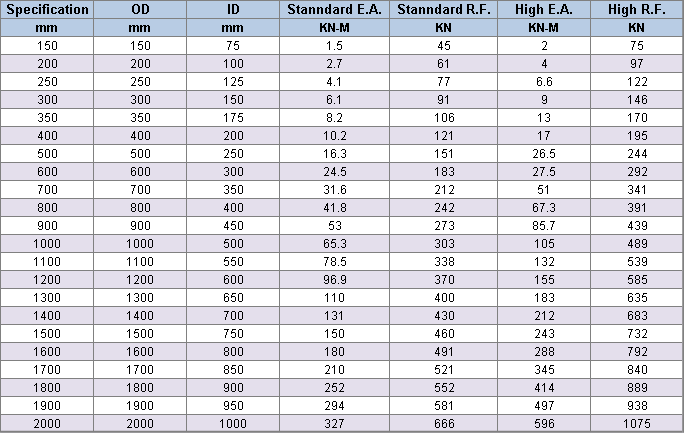
    Performance and dimension of cylindrical marine rubber fenders

    welcome to visit:
    Super Cone Rubber Fenders, Super Cell Rubber Fenders, D Type Marine Rubber Fenders, Super Arch Rubber Fenders

    As well as foam filled marine fenders

    [divider scroll_text=”SCROLL_TEXT”]

    By Ronsen Marine Uncategorized
  • 10 Jul

    Support Chain Through Mooring Offshore Buoys

    “General surface support buoys mainly have three types which are pick-up buoys, chain-through buoys and cylindrical buoys”

     
    Construction of General Surface Support Buoys

    Ronsen general surface support buoys are manufactured with high quality closed-cell PE/EVA resilient foam core, encapsulated with self-coloured polyurethane elastomer skin.

    A. Laminated closed cell resilient foam core, unsinkable design

    Cylindrical support buoys are made with highest quality closed-cell PE/EVA foam. This resilient foam make the buoys self fendering with high impact absorption capacity. Even the skin was punctured, it also is unsinkable without absorbing water. With our unique laminating process, each foam core is integrity. The foam core cannot be ruptured after long time service.

    B. Tough nylon filament reinforced polyurethane skin

    Cylindrical Buoy’s  skin is constructed of polyurethane elastomer which is reinforced with nylon filament. The polyurethane skin is unique elastomer specifically for offshore applications. It is high resistance to abrasion, fatigue and ultra violet degradation and is significantly more durable.

    C. Steel work and end assembly

    Through central tube with longitudinal gussets and extend load distribution flanges at each end, epoxy coated or hot-dpped galvanized, are encased in a closed-cell urethane foam central body. Optional bail eye, clevis eye, swivel, chain locking plate, single locking pin end fitting are available.

    Specification
    Cylindrical Buoys (RS-CB)

    Chain Through Buoys (RS-CTB)

    Pick Up Buoys (RS-PUB)


    By Ronsen Marine Uncategorized
1 2 3 4 5
About Comapny
OrangeIdea was founded in 2011. With a growing team of 17 professionals we are setting new standards in WordPress themes and template business.