News

  • 20 Jun

    What Is Cylindrical Buoys?

    Cylindrical Buoys

    As the professional China Manufacturer of ship launching airbags, pneumatic rubber fendersfoam filled fenders and arch rubber fenders, we supply cylindrical chain support buoys also for our clients.

    Sea surface buoy is a landmark device floating on the sea surface, mainly used to mark waterways, divide water areas, or mark specific locations, providing spatial reference for ship navigation, marine scientific research, and resource development. Its core function is to continuously transmit position information and reduce navigation risks in complex sea conditions through its striking appearance and stable floating performance. According to different application scenarios, offshore buoys can be divided into waterway buoys, meteorological buoys, scientific research buoys, and other types. Among them, rolling plastic buoys have become a common choice for offshore operations due to their strong weather resistance and low maintenance costs.
    1、 Structural Design and Technical Principles:
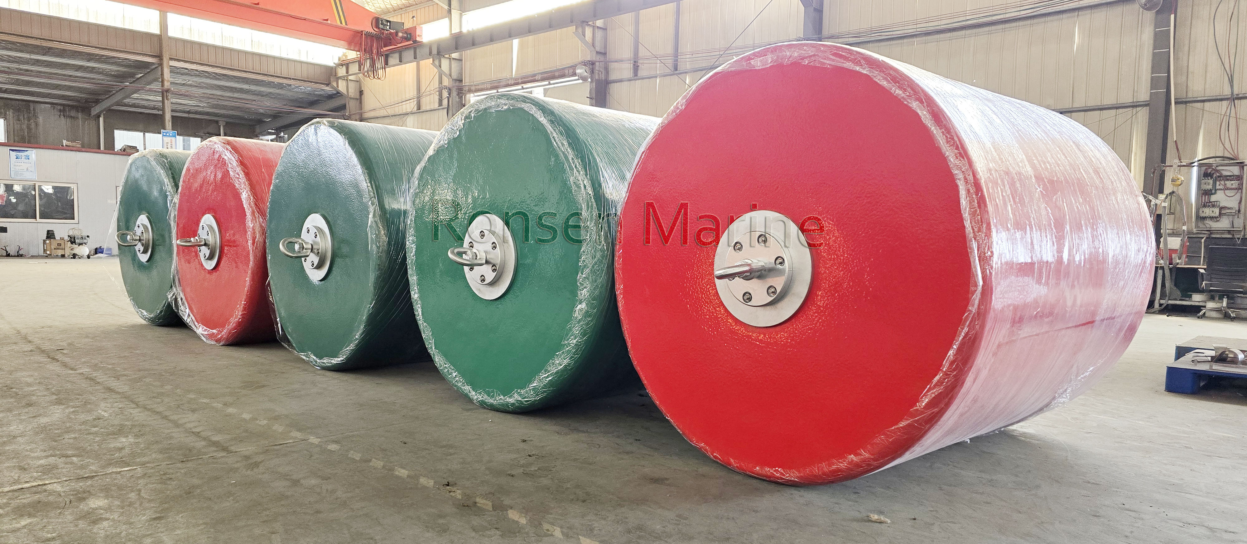
    Sea surface buoys usually consist of three parts: the float, the identification system, and the anchoring device. The floating body is formed by rotational molding process, using high-density polyethylene (HDPE) as raw material. The plastic particles are melted and uniformly attached to the inner wall of the mold through high temperature heating, and after cooling, a hollow structure is formed. This process endows the floating body with seamless, impact resistant, and corrosion-resistant characteristics, making it suitable for long-term seawater erosion and ultraviolet radiation. The identification system often uses orange or red high reflective coatings, and some models are equipped with solar LED lights to ensure night visibility; The anchoring device is connected to the sinking block through steel cables or chains to keep the buoy vertically stable and avoid being overturned by wind and waves.
    2、 Anti aging and adaptability optimization:
    In view of the characteristics of high salinity, high humidity and strong ultraviolet ray in the marine environment, the anti oxidant and ultraviolet absorber are added to the materials of the rotomolding buoy to form an anti-aging coating. Experimental data shows that the service life of such buoys in coastal areas can reach more than 10 years, far exceeding traditional metal or wooden buoys. In addition, polyurethane foam can be filled inside the floating body, which can not only increase buoyancy but also prevent water seepage. Even if the outer layer is damaged, it can still remain floating. In terms of color selection, orange and red have the highest contrast in the seawater background, which meets the visual identification standards of the International Association of Navigational Aids (IALA).
    3、 Customized applications and operating standards:
    The cylindrical buoy supports customized design of size, color, and identification system. For example, research buoys can be equipped with sensor modules to monitor real-time data such as water temperature, salinity, and wave height; Channel buoys can adapt to different water depths and flow velocities by adjusting the volume of the float and the weight of the anchor system. Attention should be paid during operation: Before installation, check the sealing of the floating body to avoid transportation damage; The anchor length should be greater than 1.5 times the water depth to prevent the buoy from being dragged and displaced; Regularly clean the surface of the floating object of biological attachment to ensure clear labeling. The customization process usually includes requirement communication, scheme design, mold making, and sample testing, with a cycle of about 15-30 working days.
    4、 Spot supply and scene coverage:
    The standardized buoy inventory specifications are complete, covering the needs of coastal and inland waterways across the country, and can be adapted from shallow water aquaculture areas to deep-sea operation platforms. The spot models mainly have a diameter of 1.2 meters to 3 meters, a buoyancy range of 500kg to 3 tons, and support 24-hour technical consultation. For special scenarios such as polar expeditions or areas with frequent typhoons, reinforced buoys can be customized to enhance their resistance to wind and waves by increasing the thickness of the float wall and anchor strength. Its self operated model ensures full process quality control from design to after-sales, reducing communication costs caused by intermediate links.

    By Ronsen Marine News Uncategorized
  • 16 Jun

    What Is the Inspection Procedure of Ship Launching Airbags?

    Ship Launching Airbags

    All ship launching airbags must meet the following test criteria.

    How is the test condition?

    Unless otherwise specified, tests shall be performed under the following conditions:

    a)  ambient temperature: 10 degree ~35 degree

    b)  media: (1) dry clean compressed air, and (2) clean fresh water for bursting test.

    Testing instruments, including pressure gauages and testing machine, shall be calibrated.

    The test shall be performed using a full-sized air bag. If the air bag is too large to be mounted on the test machine, the test may be performed on a scaled-down air bag. In order to maintain a proper representation of the full-sized sample airbag, the diameter of the scaled-down air bag shall be no less than 1/2 of the full-sized sample air bag diameter while the length (L) shall be no less than 3 times the diameter of the scaled-down air bag.

    Compression Test

    Compression test under the initial internal pressure specified in Table 3 should be carried out after the tests of 5.1, 5.2, 5.3 and 6.3

    The air bag is to be put on a press with large enough width and length to ensure that all parts of the compressed air bag is within the press. The test should be conducted as follows:

    a) fill the air bag to the initial pressure in Table 3, start the test machine and press the air bag perpendicularly till the percentage deformation reaches 70%. Observe to see if the air bag is functioning properly;

    b) gradually reduce the compressive force on the air bag until the air bag, by its own flexibility, returns to the height of its original state. Record the internal pressure;

    c) apply a compressive force perpendicularly to the air bag again, till the percentage deformation reaches 70%

    During the course of compressing and releasing, the reaction forces, internal pressures and deformation rate should be recorded at every 10% deformation interval.

    The compression performance curve of a QG6 air bag is shown in Figure A.1. The rated working pressure of the air bag is as specified in Table 3.

    By Ronsen Marine News Uncategorized
  • 13 Jun

    What is Marine Airbags?

    Ship Launching AirbagsShip Launching Airbags are also referred to Marine Airbags, which is a ship operation equipment made of high-strength rubber and synthetic fiber, featuring a reinforced layer of fabric and wear-resistant rubber structure. It includes an inflation valve and a tow-end assembly, generating buoyancy to support the ship’s weight through inflation. Its production complies with the JT/T 302-1996 “Technical Specification for Marine Airbags,” and has obtained international certifications such as from China Classification Society and French Bureau Veritas. It is primarily used in scenarios like ship launching, caisson transportation, and heavy cargo handling, capable of withstanding the launching pressure of vessels with a deadweight tonnage of 100,000 tons. The burst pressure exceeds industry standards, and the air tightness pressure loss is less than 3% within 24 hours.

    Marine Airbags
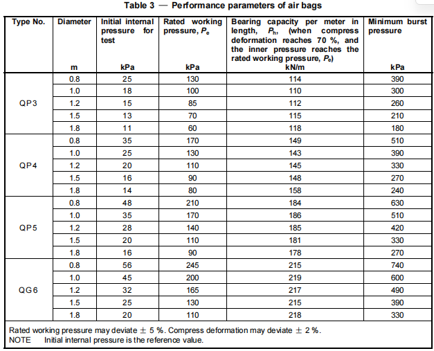
What is bearing capacity of air bag?

    It is maximum load carrying capacity of the air bag, while it suffers no permanent deformation or damage

    What is body of air bag?

    It is cylindrical part of the air bag after being fully inflated with compressed air

    What is burst pressure?

    It is internal pressure at which the air bag bursts

    What is diameters of air bag?

    It is diameter of the air bag body

    What is head of air bag?

    It is conical parts connecting the body and the mouth of the air bag

    What is initial internal pressure?

    It is air pressure that fully inflates the air bag, before compression

    What is length of air bag?

    It is lenght of the air bag body

    What is mouth of air bag?

    It is metal valves mounted on both ends of the air bag for charging air

    What is percentage of deformation?

    It is ratio of the deformed height to the original diameter of the air bag while the air bag is being compresssed

    Ship Launching Marine AirbagsP= (D-H)/D

    Where

    P is the percentage deformation(%)

    is the original diameter of the air bag (%)

    H is the height of the compressed air bag (m)

    What is rated working pressure?

    It is maximum allowable internal pressure of the air bag while supporting a weight or load equal to the rated bearing capacity of the air bag

    What is Synthetic-tire-cord layers?

    It is reinforced layer of the air bag which is made of rubber coated synthetic-tire-cord fabrics

    What is total length of air bag?

    It is overall length of the air bag

    What is the type and model of air bags?

    Marine air bags are categorized by the following two types according to the bearing capacity, per meter in lenght:

    a) QP – ordinary air bag’

    b) QG – high-bearing capacity air bag

    What is the size of ship launching airbags?

    Diameters of air bag (d) varies such as 0.8m, 1.0m, 1.2m, 1.5m and 1.8m, etc.

    Length of air bag (L) is to be specified by the user.

    By Ronsen Marine News Uncategorized
  • 04 Jun

    What Is a Floating Pneumatic Rubber Fender?

    Floating pneumatic rubber fender
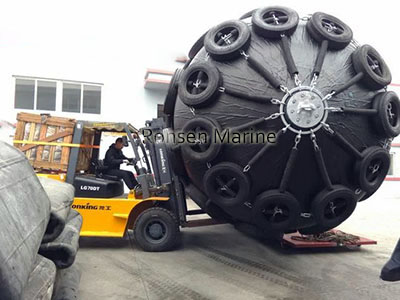
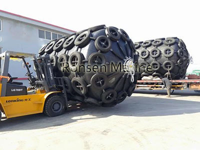
Floating pneumatic rubber fender is fender which is made of synthetic-cord-reinforced rubber sheet with compressed air inside to enable it to float on the water and work as a shock absorber between to ships, or between ships and berthing structures when they come alongside each other on the water. This high pressure
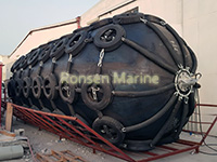
 floating pneumatic rubber fenders have sometimes been colloquially referred to as “Yokohama fenders” or  “Yokohama type fenders”.

    What is Outer Rubber?

    It is rubber layer that covers the outside of the pneumatic fender to protect the cord layers and the inner liner rubber from abrasion and other external forces

    What is Inner Rubber?

    The liner of rubber membrane that seals the pressurized air inside the fender

    What is synthetic-tyre-cord layer for reinforcement

    Layer made of synthetic-tyre-cord fabric, which maintains the internal air pressure of the fender. As the main fibres of the synthetic-tyre-cord fabric are not braided like synthetic canvas fabric or synthetic belt fabric, there are advantages for its fatigue-resistanceperformance and pressure-holding performance.

    Where is the bead ring?

    Steel ring which is placed at one end (or both ends) of the fender and holds the end of cord layers

    Where is the flange opening?

    Steel flange, which is mounted on the pneumatic rubber fender, to which an air valve or safety valve can be adapted

    What is guaranteed energy absorption?

    It is energy that the floating pneumatic fenders can absorb without permanent deformation or failure

    What is reaction force?

    It is force produced by a fender reacting to a compressive force, the reactive force is equal to the force of the air pressure of the fender multiplied by the area of the fender in contact with the ship or berthing structure

    What is the initial internal pressure?

    It is air pressure at which can uncompressed fender operates

    What is endurable pressure?

    It is inner pressure at which a fender bursts

    What is net-type floating pneumatic fender?

    It is fender which is covered by a protection net consisting of either chain, wire or fibre  and usually with tyres or rubber sleeves.

    What is sling-type pneumatic rubber fender?

    It is a fender which is designed to be used without a protection net

    By Ronsen Marine News Uncategorized
  • 30 May

    3.3 x 6.5 Floating Pneumatic Rubber Fenders

     Floating pneumatic rubber fenders is type of floating yokohama type pneumatic rubber fenders working as shock absorbers for ship to ship and ship to quay transfers when they come alongside each other on the water. It is made of synthetic-cord-reinforced rubber sheet and compressed air inside to enable it float on the water. Our company, Qingdao Ronsen Marine Supplies Co.,Ltd, are the professional manufacturer of marine airbags, pneumatic rubber fenders, foam filled fenders and offshore buoys in China. Our floating pneumatic rubber fenders are divided into sling tpe, net type, hydro and ribbed types. We manufactured and tested the pneumatic fenders strictly according to International standard ISO 17357-1:2014.

    The design and selection of floating fenders can be confirmed as per the maximum energy absorption of specific conditions. We should calculate and compare the requirements for the energy of the following condition. The kinetic energy when the ship berthing or after berthing, the energy of relative motion of ship to ship and ship to wharf.

    Ship to ship operation of floating pneumatic fenders

    Following the follow chart which simply demonstrate the procedure of floating fenders selection.

    There is a quick reference to do the floating pneumatic rubber fender selection tentatively as per the listed OCIMF table. If the energy absorption of the tentative selected yokohama fender(Ef) is larger than the calculatedd berthing energy (E). It means that a suitable floating fender selection has been made. If the Yokohama fenders energy absorption capacity is less than the calculated berthing energy. The selected yokohama fenders should be upgrated and selected again.

    OCIMF Table Selection of Floating Pneumatic Rubber Fenders

    It is a quick reference selection based on 50 kPa (Pneumatic 50) and calm condition, Equivalent Displacement coefficient (C) should be calculated firstly, then make the tentatively selection as per OCIMF ship to ship transfer guide.

    C= 2 x Displacement ShipA x Displacement ShipB/( Displacement ShipA + Displacement ShipB)

    Berthing Energy Calculation of Yokohama Fenders

    The berthing energy can be calculated by the following formula:

    Where:

    E =Berthing Energy (in KNm or ton/m)

     = Equivalent Displacement Coefficient

     = Relative Approaching Velocity

     = Eccentricty Factor

    SF = Safety Factor

    Where:

     = Water displacement of the berthing Ship A ( tons )

     = Water displacement of the berthing Ship B ( tons )

     = Added mass coefficient of Ship A

     = Added mass coefficient of Ship B

    Added Mass Coefficient

    or

    Where:

    d = Full load draft (m, ft)

    B = Molded Breadth (m, ft)

     = Block coefficient

    Safety Factor

    A safety factor (SF) value from 1.0 to 2.0 for the berthing energy shall be considered for abnormal berthing conditions.

    Eccentricity Factor

    Where:

    I = Radius of rotation of the vessel (usually 1/4 of the vessel’s length )

    r = Distance of the line paralleled to wharf measured from the vessel’s center of gravity to the point of contact

    a = the angle degree

     = Block coefficient

    L = Length of ship

    Relative Approaching

    The berthing energy needs to be calculated considering weather conditions, categorized by the three conditions calm, moderate and rough, and the approaching velocity to calculate the berthing energy are assumed to be as the follow table. These information are obtained from various industry references and standards.

    Ship to Quay Operation of Pneumatic Rubber Fenders

    The selection and installation of floating pneumatic rubber fenders (marine fendering) system for a quay is determined based on several design parameters for each ship berthing and mooring condition

    The energy can be calculated by the following formula:

    Where:

    E = Berthing Energy ( in KNm or ton/m)

    M = Displacement (ton)

    V = Berthing Velocity (m/s)

     = Eccentricity Factor

     = Vitural mas factor

    d = Full load draft (m, ft)

    B = Molded Breadth (m. ft)

    SF = Safety Factor

     = Berthing configuration factor

    This is the portion of berthing energy which is absorbed by the cushion effect of water between the approaching vessel and the quay wall. The smaller the draft of the vessel is, or the larger the under keel clearance, the mor trapped water can escape under the vessel, and would give a higher  value. Also, if the berthing angle of the vessel is greater than 5 degree, we can consider  = 1

     = Softness coefficient

    This is the portion of berthing energy which is absorbed by the demonstration of the vessel’s hull and fender. When a soft fender is issued  = 0.9

    We have 3 units floating pneumatic rubber fenders 3.3m x 6.5m ready which is for our client. These fenders are equipped with truck chains tire nets and intial pressure is 50kPa, we take 20 days around to prepare the 3 units peumatic fenders. They are to be shipped to Spain which would be used for the berthing of ships. As the specialized china supplier of marine fenders, we not only supply floating pneumatic rubber fenders but also foam filled fenders, foam filled buoys and marine airbags which are widely used in the oil&gas field.

    By Ronsen Marine News
  • 18 May

    Rubber Foam Filled Fenders for World Biggest Crane Ship

    Rubber foam filled fenders is a new type of foam filled fenders. Comparing with traditional foam fenders, rubber type foam fenders has superior stronger rubber skin than polyurethane elastomer skin, which are recognized as the toughest foam fenders in global marine industry nowdays.

    Blue Whale Vessel, as the world’s biggest crane ship, belongs to CNOOC Ltd. (NYSE:CEO) (CEO NYSE; 0883.HK), is 241 m in length, 50 m in width, 20.4 m in depth and 64,110 tons total weight. This crane ship is constructed by ZPMC, its maximum lifting capacity can reach to 7,500 tons, equal to the weight of steel tower Eiffel Tower in France.

    As the professional manufacturer of marine fenders & marine rubber airbags (MRA) in China, Ronsen Marine has been leading in the development and improvement of foam fenders since 2006. Lower maintenance of Ronsen resilient foam fenders is a basis for vessels working under severe weather conditions and hard surroundings. Rubber Foam Fenders’ vulcanizing natural rubber skin’s resistant to ozone and ultra violet light as well as its particular filament wraps, filament reinforcing are guaranteeing higher energy absorption and lower reaction force. Rubber Foam Fenders shows its advantage extremely and clearly.

    Therefore, Ronsen Marine was awarded this business opportunity to provide 6 units standard capacity foam filled fenders 3.3 m x 6.5 m to Blue Whale.

    By Ronsen Marine News