• 22 Aug

    What is a D Rubber Fender? The Complete Guide to D-Type Marine Fenders

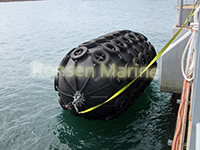
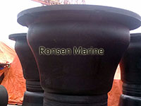
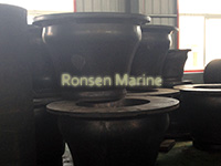
    D rubber fenders
    D rubber fenders

    If you’ve ever watched a large ship dock, you’ve seen the silent workhorses that make it all possible: rubber fenders. Among the many types available, the D rubber fender (often simply called a “D fender”) is one of the most common and versatile. This guide explains everything you need to know about D-type rubber fenders, from their basic definition to their key benefits and typical uses.

    What is a D Rubber Fender?

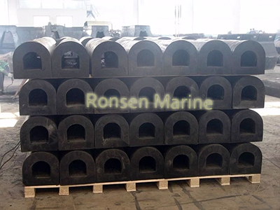
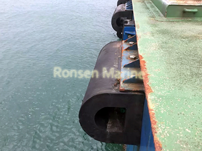
    A D rubber fender is a marine bumper named for its “D”-shaped cross-section. Unlike cylindrical fenders which are round, the D fender features a flat back and a curved, semi-circular front. This shape is not just for aesthetics—it is a functional design that offers unique advantages for berthing and mooring operations.

    Typically made from high-quality extruded rubber, D fenders are known for their simplicity, durability, and ease of installation. They are often bolted directly to the side of a dock or vessel, providing a reliable cushioning effect.

    How Does a D Rubber Fender Work?

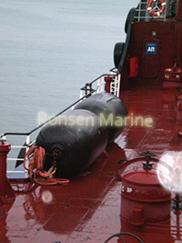
    D fenders
    D fenders

    The primary function of any rubber fender is to act as a buffer that absorbs kinetic energy. When a ship makes contact with a dock, it carries significant momentum. Without protection, this impact can damage both the vessel’s hull and the port infrastructure.

    Here is how a D rubber fender works:

    1. Energy Absorption: When a vessel hits the fender, the curved front of the “D” shape compresses. This compression absorbs the ship’s berthing energy.
    2. Force Reduction: By absorbing this energy, the fender reduces the reaction force transferred back to the ship and the dock, minimizing the risk of structural damage.
    3. Impact Distribution: The fender helps distribute the impact load over a larger area of the ship’s hull, preventing concentrated stress points that could cause indentation or cracking.

    Key Benefits and Characteristics of D Fenders

    D fenders are a popular choice in the maritime industry for several reasons:

    · Simple and Easy Installation: They can be securely mounted using bolts or flat steel fasteners directly to the structure.
    · High Durability: Made from tough rubber compounds like natural rubber, SBR, or EPDM, they resist seawater, sunlight, and ozone, ensuring a long lifespan.
    · Wide Range of Applications: They are suitable for various vessels and dock types.
    · Customization: D fenders can be extruded in long lengths and cut to size, drilled, or even pre-curved to meet specific project requirements.
    · Cost-Effective: Compared to more complex fender systems like cell or cone fenders, D fenders are generally an affordable and effective solution for lower-impact applications.

    Common Applications: Where Are They Used?

    Because of their versatility, D rubber fenders are used across the maritime industry:

    · Tugboats and Workboats: They are frequently installed along the hulls of tugboats, ferries, and patrol boats that make frequent contact with other vessels and docks.
    · Small Docks and Harbors: D fenders are an excellent choice for fishing harbors, marinas, and inland waterway docks where smaller vessels are present.
    · Jetties and Wharves: They offer reliable protection for small craft jetties and general-purpose wharves.
    · As a Protective Band: Small to medium-section D fenders are often used as a continuous protective band along the structures of workboats and barges.

    D Fenders vs. Other Types

    While D fenders are highly effective, they are best suited for specific scenarios. Here is how they compare to other common rubber fenders:

    [supsystic-tables id=14]

    How to Choose the Right D Rubber Fender

    Selecting the correct fender involves considering several factors:

    1. Vessel Size and Weight: Larger, heavier ships generate more berthing energy and may require larger or more D fenders.
    2. Docking Speed: The speed at which the vessel approaches the dock directly impacts the energy that needs to be absorbed.
    3. Dock Structure: The type of dock or pier and the available mounting space will influence your choice.
    4. Environmental Conditions: Consider the weather, water salinity, and UV exposure to select the appropriate rubber compound.

    Conclusion

    The D rubber fender is a fundamental component of marine protection. Its simple, effective design offers a robust and economical solution for protecting vessels and dock structures in a variety of low-to-medium-impact scenarios. Whether used on a tugboat or a small harbor dock, the D fender remains a trusted choice for maritime professionals worldwide.

    By Ronsen Marine Uncategorized
  • 22 Aug

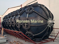
    Pneumatic vs Foam Fenders

    Pneumatic vs Foam Fenders: Which Marine Fender Actually Fits Your Berth (2026 Guide)

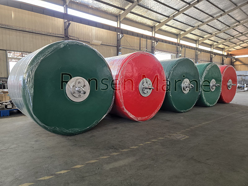
    Foam Fenders
    Foam Fenders

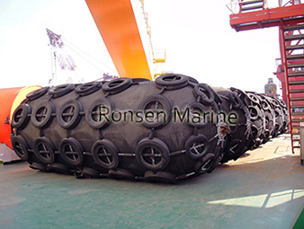
    Choosing between pneumatic and foam-filled fenders is not a spec-sheet footnote—it decides how much downtime, puncture repair, and hull-pressure risk your port, yard, or offshore project absorbs over the next 10 years. Both are “marine fenders,” but they behave nothing alike under cyclic wave load, STS impact, or permanent pile mooring.

    This guide breaks down the real-world difference, when each type fails, and how we at Ronsen Marine specify them for clients running ports, OSV fleets, and yacht pontoons.

    What Is a Pneumatic Fender?

    A pneumatic fender is an inflatable, compressed-air marine fender built from reinforced rubber-nylon plies (Yokohama-type). Impact energy is absorbed by air compression, giving a low reaction force / high energy absorption curve that is friendly to lightweight hulls.

    Core traits

    • Air-filled, needs inflation pressure checks (typically 50–80 kPa)
    • Linear load-deflection, excellent under cyclic (wave) conditions—air doesn’t creep
    • Lightweight, easy to relocate, popular for STS (ship-to-ship) and temporary berths
    • Puncture = loss of performance; needs spare units and patrol inspection

    Ronsen’s pneumatic rubber fender line follows ISO 17357-1S/2S geometry for STS and quay use.

    What Is a Foam-Filled Fender?

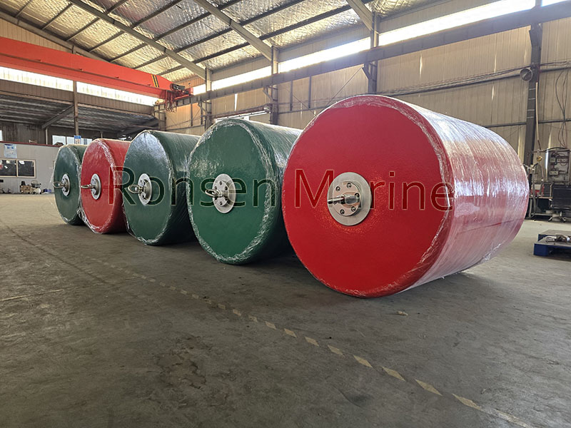
    Pneumatic Fenders
    Pneumatic Fenders

    A foam fender has a closed-cell EVA/PE foam core wrapped in polyurea/PU skin with nylon reinforcement—no air, no inflation. Energy is absorbed by foam compression.

    Core traits

    • Unsinkable, zero puncture risk, zero pressure maintenance
    • Higher abrasion/UV/oil resistance via polyurea skin—good for high-traffic docks
    • Heavier, higher upfront cost, but near-zero lifecycle service
    • Foam slowly recovers after compression; under permanent cyclic load it can creep, so it’s better as floating/offshore than fixed permanent pile fender

    Ronsen builds netless sling type, cushion netted (chain+tire), donut pile fenders, and suitcase pendant foam buoys for offshore mooring.

    Pneumatic vs Foam Fenders: Side-by-Side

    [supsystic-tables id=11]

    When to Pick Pneumatic

    • Ship-to-ship transfer where fenders move between vessels daily
    • Large tankers/bulk carriers needing low hull pressure at high energy
    • Temporary project berths (dam construction, salvage) where you deflate and redeploy
    • Budget-sensitive first buy with crew available for weekly pressure checks

    When to Pick Foam-Filled

    • Offshore platforms, windfarm SOVs, OSV side fendering—no one wants a midnight puncture
    • Pile/donut applications with tidal rise-fall and turning dolphins
    • Yacht marinas and barge fleets where “maintenance-free” beats “cheap”
    • High-abrasion environments (tire nets, construction barges, rock dumping)

    Rule of thumb: pneumatic wins on cyclic permanence + portability; foam wins on abuse tolerance + zero maintenance.

    Common Spec Mistakes Buyers Make

    1. Sizing by diameter only—ignore energy/reaction curve vs hull panel strength.
    2. Using foam fenders as fixed permanent fenders under constant swell (creep risk).
    3. Running pneumatic fenders with no spare—one puncture halts berthing.
    4. Ignoring skin chemistry: polyurea > old PU for oil + UV zones.

    FAQ

    Are foam fenders better than pneumatic?

    Not universally. Foam is better for maintenance-free offshore/pile use; pneumatic is better for cyclic STS and portable deployment.

    Do foam fenders sink if damaged?

    No. Closed-cell EVA/PE core stays buoyant even if skin is cut—unlike pneumatic, which deflates.

    Can pneumatic fenders be used permanently?

    Yes, but only with scheduled pressure checks and spare inventory; air fatigue is not the issue—rubber-nylon body wear and punctures are.

    Which is cheaper long term?

    Foam usually wins TCO over 8–10 yrs because no puncture repair, no spares rotation, no labor patrol.

    Does Ronsen make both types?

    Yes—pneumatic rubber fenders (ISO Yokohama type) and foam-filled fenders (netless, netted, donut, shipboard portable). See Ronsen foam fenders and pneumatic range.

    By Ronsen Marine Uncategorized
  • 22 Aug

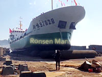
    How Shipyards Choose the Right Marine Airbags

    How Shipyards Choose the Right Marine Airbags: Step-by-Step Selection Guide

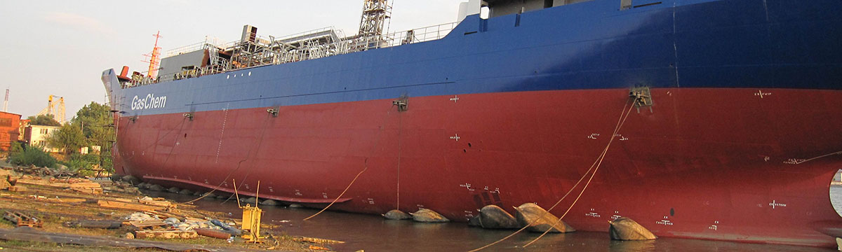
    Shipyard marine airbags
    Shipyard marine airbags

    Choosing the right marine airbags is the difference between a safe 2-hour vessel launch and a hull-damaging, insurance-triggering failure. Modern shipyards no longer treat ship launching airbags as commodity rubber tubes—they specify them like structural components.

    This guide breaks down how shipyards choose the right marine airbags using vessel parameters, ISO 14409 compliance, diameter/ply math, layout logic, and supplier vetting.

    Why Airbag Selection Is an Engineering Decision

    Marine rubber airbags bear the full displacement weight of a vessel across a deformed contact patch. Undersize them and you get:

    • Excessive compression (>30%) → cord-layer fatigue
    • Pressure spike beyond working pressure → burst risk
    • Uneven hull support → keel bending stress
    Shipyard ship launching airbags
    Shipyard ship launching airbags

    A correct selection balances rated working pressure (WP), bearing capacity per meter (kN/m), diameter vs block height, and number of bags × spacing.

    Step 1: Define the Vessel Parameters First

    Never size an airbag before locking these:

    [supsystic-tables id=12]

    Example: a 440-ton Ro-Ro ferry (Lpp 42.5 m, B 12.5 m, Cb 0.55) needs a different matrix than a 8,000 DWT barge.

    Step 2: Use the Standard Sizing Logic (Diameter → Length → Ply)

    Diameter (D)

    Rule of thumb from yard practice:

    Airbag diameter should be at least 0.3–0.5 m larger than keel block height so the hull clears blocks before rolling.

    Factory marine airbags
    Factory marine airbags

    Common diameters: 0.8 m, 1.0 m, 1.2 m, 1.5 m, 1.8 m, 2.0 m, up to 2.5 m.

    Effective Length (EL)

    EL must be ≥ vessel beam for single-row layout; if EL < beam, use staggered or double-row.

    Standard EL: 6–18 m (custom to 24 m+).

    Cord Layers / Ply Rating

    Ply count sets working pressure and bearing capacity:

    [supsystic-tables id=13]

    A 1.5 m × 15 m 6-layer bag runs ~0.13–0.18 MPa WP and ~110–140 kN/m bearing at safe compression.

    Step 3: Run the Bearing-Capacity Check

    Simplified selection formula used in yard engineering:

    N = K1 × Q × g / (Cb × R × Ld) + N_backup

    • N = number of airbags
    • K1 = safety factor ≥ 1.2
    • Q = vessel weight (ton)
    • R = allowable unit bearing capacity (kN/m)
    • Ld = effective contact length per bag (m)
    • N_backup = 2–4 spare bags

    If calculated compression at WP exceeds ~25–30% of D, go up one diameter or add one ply layer.

    Step 4: Verify ISO 14409 and Class Certifications

    Shipyards procuring for classed projects must reject non-certified bags. Minimum checks:

    • ISO 14409:2011 – international standard for ship launching air bags (materials, burst test, compression-recovery, marking)
    • Class society approval – CCS, BV, DNV, ABS, LR depending on flag
    • Mill test reports – rubber tensile ≥18 MPa, elongation ≥400%, cord strength traceability
    • Burst pressure ≥ 2× WP, reputable makers run 3× test

    Qingdao-based ISO 14409 factories dominate export supply, but audit before bulk order.

    Step 5: Match Airbag Layout to Hull Geometry

    Selection is not just per-bag—it is system layout:

    • Single row – EL ≥ beam
    • Staggered – 0.5×beam ≤ EL < beam
    • Double row – beam > 2×EL, or catamaran/barge
    • Center spacing ≤ 6 m for steel hulls, min spacing ≥ πD/2 + 0.3 m
    • Pre-inflation leak test: <5% pressure loss in 1 h

    Step 6: Vet the Supplier Like a Class Surveyor

    A shipyard’s purchasing checklist:

    1. 10+ years dedicated airbag production (not general rubber)
    2. Provides calculation sheet for your vessel, not just a quote
    3. OEM options: valve type, end ring, 1260D/1670D cord, color marking
    4. Warranty 12 months + on-site launch support availability
    5. Reference project list with DWT and launch method (side/end/haul-out)

    Low price per bag is irrelevant if WP is overstated by 0.02 MPa.

    Quick Selection Cheat Sheet

    • Fishing boat 30–80 ton → D1.0×L10m, 4-layer, 5–6 pcs
    • 300 ton workboat → D1.2×L12m, 6-layer, 6–8 pcs
    • 2,000 ton landing craft → D1.5×L15m, 6-layer, 10–12 pcs
    • 10,000 DWT barge → D1.8–2.0m, 7–8 layer, 14–18 pcs staggered
    • 50,000+ DWT → engineered matrix, 2.0–2.5 m, QS grade, class-witnessed

    Always add 2–4 backup airbags per launch.

    FAQ (Snippet Targets)

    How do shipyards calculate marine airbag quantity?

    Using vessel weight, block coefficient, contact length, and allowable kN/m bearing, with a safety factor ≥1.2 and 2–4 spare bags.

    What ply rating is best for ship launching?

    4–5 ply for small boats, 6–8 ply for mid-size vessels, 9–10+ for heavy barges and large ships. Ply count tracks working pressure.

    Is ISO 14409 mandatory?

    Not by law everywhere, but required by most classed shipyards and international buyers. It governs materials, burst test, and marking.

    Can one airbag size fit all launches?

    No. Diameter depends on block height, length on beam, ply on weight. Reusing wrong-size bags is a top cause of launch incidents.

    By Ronsen Marine Uncategorized
  • 14 Aug

    What is an Arch Rubber Fender

    What Is an Arch Rubber Fender? The Practical Engineer Guide (2026)

    Cone Rubber Fenders
    Cone Rubber Fenders

    An arch rubber fender is a solid, arched-cross-section marine fender mounted on quays, pile dolphins, lock walls, or vessel hulls to absorb berthing energy and lower reaction force during docking. Its curved profile spreads impact across a wider face than a flat D-fender, yet stays simpler and cheaper than a cone or cell unit—making it the default choice for fishing harbors, ferry terminals, workboat jetties, and retrofit projects under roughly 10,000–50,000 DWT.

    This guide explains what it is, how it absorbs energy, where it beats (or loses to) cone and cell fenders, and how to size one using PIANC / ISO 17357 logic.

    What Is an Arch Rubber Fender (Definition)

    An arch rubber fender is a single-piece molded solid rubber element with an inverted-U or arch cross-section. It is bolted to a steel mounting plate, often with a UHMW-PE front face panel to cut hull friction.

    Core parts:

    • Rubber body – natural rubber (NR) / SBR blend, 60%+ NR content for 15–20 yr life
    • Steel base plate – anchors to concrete or steel quay
    • Optional UHMW-PE pad – low-friction contact face
    • Bolts / shear chains – resist pull-out and lateral shear
    Cone Fenders
    Cone Fenders

    Unlike pneumatic or foam fenders, it has no air, no bladder, no moving parts—just elastic deformation.

    How an Arch Rubber Fender Works

    When a vessel touches the berth:

    1. The arch cross-section compresses vertically, converting kinetic energy into heat inside the rubber.
    2. The curved legs spread reaction force sideways, avoiding stress concentration on the quay face.
    3. At rated deflection (usually 50–60% of free height), it returns most of its shape—no permanent set if within design load.
    4. UHMW-PE face lets the hull slide instead of gripping, reducing berthing shear.

    Typical solid-rubber arch performance band:

    • Energy absorption: 15–80 kJ per unit (small–medium berths)
    • Reaction force: moderate, higher than cone, lower than cylindrical
    • Hull pressure: low–moderate
    • Service life: 10–20 years with 6-month visual checks

    Arch Fender vs Cone vs Cell (Quick Table)

    [supsystic-tables id=10]

    Arch wins on price + simplicity; loses on energy density per kg.

    Where Arch Rubber Fenders Are Used

    • Fishing ports and small craft harbors
    • Ferry terminals and Ro-Ro side berths
    • Workboat / pilot boat jetties
    • Lock chamber walls and corner dolphins
    • Retrofit of old quay walls with low allowable reaction
    • Inland barge terminals

    They are not for 100k+ DWT tankers or high-velocity VLCC berths—use cone or cell there.

    How to Size an Arch Fender (PIANC Logic, Simplified)

    You do not guess size from a photo. Use the standard berthing energy formula:

    E = 0.5 × Cm × M × Vb² × Ce × Cc × Cs

    Where:

    • Cm = added mass factor (1.3–2.0)
    • M = vessel displacement (tonnes)
    • Vb = normal berthing velocity (m/s)
    • Ce / Cc / Cs = eccentricity, configuration, softness factors

    Then:

    1. Calculate design energy E (kN·m)
    2. Pick arch unit whose catalog energy at 50% deflection ≥ E
    3. Check reaction force R ≤ quay allowable
    4. Check hull pressure ≤ class approval (usually < 200 kPa for small craft)
    5. Space units at ≤ 12–15 m or 0.15 × vessel length

    💡 Most specifiers oversize by 20–30% for tidal skew and operator error.

    Installation & Maintenance Basics

    Install:

    • Mount above low-tide line for inspection
    • Torque bolts 100–200 Nm, re-check after 3 months
    • Horizontal on straight walls, vertical on piles, angled at corners
    • Add shear chain if tidal range > 3 m

    Maintain:

    • Visual check every 6 months (cracks, abrasion, bolt rust)
    • Clean salt/debris quarterly
    • Re-coat steel parts per ISO 12944 every 2–5 yrs
    • Replace if deflection recovery drops below 50% of rating

    Arch Rubber Fender FAQ

    Is an arch fender the same as a D-fender?

    No. Arch has a taller curved leg profile and better energy-per-kilo; D-fender is a flattened D-shape for light craft and narrow edges.

    What rubber quality should I specify?

    Minimum PIANC G3-type compound: tensile ≥15 MPa, elongation ≥350%, hardness 60±5 Shore A, compression set ≤25% after 70°C×22h.

    Can arch fenders handle angled berthing?

    They tolerate small skew (≤5°) acceptably. For 10°+ angular hits, cone fenders are better.

    How long do they last?

    10–15 yrs in high-traffic fishing ports, 15–20 yrs in moderate ferry use, if virgin NR blend and not overloaded.

    By Ronsen Marine Uncategorized
  • 11 Aug

    How do Pneumatic Rubber Fenders Work?

    How Do Pneumatic Rubber Fenders Work?

    Pneumatic Rubber Fenders
    Pneumatic Rubber Fenders

    A pneumatic rubber fender works by compressing trapped compressed air inside a reinforced rubber cylinder to convert a ship’s kinetic berthing energy into increased internal air pressure and elastic rubber deformation. Because air is highly compressible, the fender absorbs large impact energy while returning a very low reaction force to the hull—then rebounds to its original shape when the load is removed.

    Also called Yokohama fenders or floating pneumatic fenders, they are the global standard for ship-to-ship (STS) transfer and floating berths under ISO 17357-1:2014.

    What Is a Pneumatic Rubber Fender?

    A pneumatic rubber fender is a hollow, cylindrical, air-filled marine buffer built from synthetic-tire-cord-reinforced rubber layers with hemispherical ends. It floats at the waterline, tethered by slings or a chain-tire net, and rises/falls with tide and swell without fixed mounting.

    Pneumatic Fenders
    Pneumatic Fenders

    Key identifiers:

    • Internal medium: compressed air (initial 50 kPa = P50, or 80 kPa = P80)
    • Body: outer rubber + synthetic cord reinforcement + inner air seal
    • Performance basis: 60% diameter deflection at Guaranteed Energy Absorption (GEA)
    • Standard: ISO 17357-1:2014

    The 4-Layer Internal Structure

    LayerMaterialJobOuter rubberSynthetic NR/SBR blendAbrasion, UV, seawater, ozone resistanceCord reinforcementNylon/polyester tire cord, crossedHolds internal pressure, stops burstInner rubberAirtight linerSeals compressed air, prevents leakageEnd flange + valveSteel + safety relief valveInflation, pressure check, over-pressure release (mandatory ≥Ø2500 mm)

    The cord layer is the “skeleton”—same principle as a truck tire. Without it, the rubber would balloon and fail.

    Sling Pneumatic Fenders
    Sling Pneumatic Fenders

    How Pneumatic Fenders Absorb Energy (Step by Step)

    1. Vessel approaches → fender floats at hull contact point.
    2. Hull presses → fender compresses axially up to 60% of original diameter.
    3. Air column shortens → internal pressure rises uniformly (P50 or P80 baseline + impact spike).
    4. Kinetic energy converts → E = \frac{1}{2}mv^2 becomes internal air pressure + rubber/cord elastic strain.
    5. Reaction force stays low → because air compresses progressively, hull sees soft cushioning, not a hard wall.
    6. Vessel retreats → air re-expands, rubber rebounds elastically, fender ready for next hit (no break-in cycle needed, unlike solid rubber).

    Under ISO 17357 parallel compression test, EA is the integral of reaction force over deflection:

    a = \int R(x)\,dx , measured to 60% deflection at ≤80 mm/min.

    Why Reaction Force Stays Low (The Core Advantage)

    Solid rubber fenders fight the hull with material stiffness. Pneumatic fenders fight with gas compressibility.

    Air has no fixed shape and no high initial modulus—so the force-deflection curve rises gently at first, then steeper near 60%. That “soft entry” is why pneumatic fenders show:

    • High EA (e.g. Ø3300×6500 mm P80 ≈ 3015 kJ at GEA)
    • Low hull pressure (P50 often 130–150 kN/m² class)
    • Minimal structural stress on LNG, VLCC, and thin-shell hulls

    P50 vs P80: Tuning by Air Pressure

    You do not change the size—you change the initial inflation pressure.

    RatingInitial pressureEA at 60% defl.Reaction forceTypical useP5050 kPaBaseline (GEA)LowestStandard STS, mid-size vesselsP8080 kPa~1.3–1.5× P50HigherVLCC/LNG, high-energy berthing

    Higher pressure = more EA, but pushes more reaction force back to hull and dolphin—so P80 must be matched to hull allowable pressure.

    Pneumatic vs Foam-Filled Fender (Working Principle)

    AspectPneumatic rubber fenderFoam-filled fenderEnergy mediumCompressed airClosed-cell foam compressionDeflation riskYes (skin/valve breach)NoneReaction forceVery lowModerate–higherAngled impactUniform pressure (fluid air)Slightly less uniformMaintenancePressure checks, valveNoneTransportDeflatable, compactBulky, solidBest fitSTS, offshore, tide swingsFixed berths, unmanned, debris risk

    Source synthesis.

    Where Pneumatic Rubber Fenders Are Specified

    • Ship-to-ship transfer (crude, LNG, product tankers)
    • Offshore platform / FPSO boat landing
    • Tidal jetties and ferry terminals
    • Naval alongside replenishment
    • Emergency berthing where no fixed fender exists

    Sizing Reminder (So the Physics Matches the Berth)

    Select by design berthing energy, not boat length:

    • Vessel displacement + approach velocity
    • PIANC WG-211 energy model
    • ISO 17357 GEA at 60% deflection
    • Hull allowable pressure → pick P50 or P80
    • Check reaction force against dolphin/wharf limit

    A 2000×3500 mm P50 fender ≈ 875 kJ EA / 128 kN/m² hull pressure—then you verify RF fits the structure.

    FAQ

    How does a pneumatic fender absorb energy without solid foam?

    It compresses sealed air inside a cord-reinforced rubber body; the air pressure rise plus rubber elasticity stores the vessel’s kinetic energy and releases it on rebound.

    What is the difference between P50 and P80 pneumatic fenders?

    P50 is inflated to 50 kPa initial pressure, P80 to 80 kPa. P80 gives 30–50% more energy absorption but higher reaction force on the hull.

    Do pneumatic fenders need maintenance?

    Yes—regular air-pressure checks (cold/warm drift), valve inspection, and net/sling wear checks. Foam fenders do not.

    Can a pneumatic fender explode?

    Not under normal use; ISO units ≥2.5 m carry automatic safety relief valves. Burst risk comes from over-inflation, fire, or ignored valve failure.

    Why are they called Yokohama fenders?

    The Yokohama Rubber Co. commercialized the floating air-filled design in the 1950s; “Yokohama-type” is now synonymous with pneumatic rubber fender.

    By Ronsen Marine Uncategorized
  • 11 Aug

    How do Foam Fenders Work?

    How Do Foam Fenders Work?

    Foam Fenders
    Foam Fenders

    A foam fender works by converting a ship’s kinetic berthing energy into reversible compression of a closed-cell foam core wrapped in a tough elastomer skin. There is no compressed air inside—so the fender cannot deflate, keeps floating after skin damage, and needs no pressure maintenance.

    When a vessel presses against it, the closed-cell EVA or polyethylene foam compresses (typically rated to 60% deflection), the reaction force rises progressively, and the hull slows down. Once the vessel moves away, the foam rebounds elastically and is ready for the next impact.

    That is the whole mechanism in one paragraph.

    The 3-Layer Structure of a Foam-Filled Fender

    Every foam fender (also called foam-filled fender or floating foam fender) uses the same functional stack:

    1. Closed-Cell Foam Core

    Foam Fender
    Foam Fender

    Made of cross-linked PE or EVA foam, thermally laminated into one solid body. Each cell is sealed independently.

    • Absorbs energy by cell compression + polymer shear
    • Water cannot enter even if the skin is cut
    • Density (~58–70 kg/m³) sets the energy/reaction balance

    2. Filament Reinforcement Layer

    A helical nylon or Kevlar cord layer sits between foam and skin to stop the coating from peeling under repeated shear—critical for STS and offshore use.

    3. Polyurethane / Polyurea Elastomer Skin

    Sprayed seamless outer shell (Shore A 75–95, tear >52 N/mm, −40 °C to +60 °C).

    • Resists UV, saltwater, oil, abrasion
    • Optional non-marking grade for cruise/yacht hulls

    Internal swivel eyes or a center tension chain take the hanging load; the foam itself only takes compression.

    The Energy Absorption Mechanism (Physics)

    A berthing ship arrives with kinetic energy:

    E = \frac{1}{2}mv^2

    The fender dissipates that energy in four steps:

    1. Hull contacts fender → local pressure rises
    2. Closed-cell foam cells compress and shear
    3. Micro gas pockets in cells add pneumatic-like cushioning without air chambers
    4. Vessel decelerates; energy is stored elastically, then released as the foam rebounds to ≥90% of original diameter within 24 h

    Unlike a pneumatic fender, performance does not drift with temperature or altitude, because there is no gas law involved—only foam modulus and geometry.

    Foam Fender vs Pneumatic Fender

    FactorFoam-Filled FenderPneumatic (Yokohama) FenderEnergy mediumClosed-cell foam compressionCompressed air (50/80 kPa)Punctured skinStill floats, still worksDeflates, loses functionMaintenanceNone (no inflation)Periodic pressure checksReaction forceModerate–high (grade-dependent)Very lowTemp sensitivityLowNoticeableBest usePermanent berths, offshore, STS, unattended sitesTemporary STS, variable hull curvesInitial costHigherLower

    Source synthesis:

    Why “Unsinkable” Is Literally True

    In a pneumatic fender, one valve or skin failure = total pressure loss.

    In a foam fender, the buoyant medium is the solid foam itself. Cut the skin, and each closed cell stays dry and buoyant. The unit keeps cushioning until you patch or re-skin it.

    That is why naval bases, LNG terminals, FPSO boat landings, and remote jetties specify foam-filled units.

    Where Foam Fenders Are Used

    • Quay and jetty berthing (vertical hung, chain sling)
    • Ship-to-ship transfer (LNG, crude, product tankers)
    • Offshore platforms, SPM buoys, FPSO boat landings
    • Ro-Ro ferries, cruise terminals (non-marking skin)
    • Floating drydock faces and lock entrances

    Sizing Note (So It Actually Works)

    Selection is not by vessel length. You need:

    • Displacement and approach velocity
    • Allowable hull pressure (PIANC WG-211: usually <200 kN/m²)
    • Design energy per PIANC/ASTM F2192
    • EA and RF at 60% deflection from the maker’s curve

    Example: a 1000 × 1500 mm foam fender is commonly ~49 kJ absorption at ~205 kN reaction at 60% deflection—then you check that RF against your hull and dolphin limit.

    FAQ

    How does a foam fender absorb energy without air?

    It compresses a closed-cell foam core; the polymer matrix and sealed cells store elastic energy, so no internal air pressure is needed.

    Do foam fenders bounce a ship back?

    They rebound elastically (≥90% diameter recovery in 24 h), but with less liveliness than pneumatic fenders—better for fixed structures, less ideal for high-angle STS roll.

    What happens if a foam fender is punctured?

    Nothing catastrophic: the skin can be patched, the core stays buoyant, and the fender keeps working until repaired.

    Are foam fenders better than pneumatic fenders?

    For unattended, debris-heavy, or offshore sites—yes. For temporary STS with strict low reaction force—pneumatic is often better.

    How long do foam fenders last?

    Quality PU/polyurea-skin units run 10–20 years; cores can be re-skinned to extend life.

    By Ronsen Marine Uncategorized
  • 11 Aug

    How do General Surface Support Buoys Work?

    How Do General Surface Support Buoys Work?

    Support Buoys
    Support Buoys

    A general surface support buoy works by displacing water with a permanently buoyant closed-cell polyethylene (PE) or EVA foam core to support the submerged weight of mooring chains, ropes, hoses, or cables—while an internal steel frame carries the tensile load and a polyurethane skin resists the marine environment. There is no air chamber to inflate or lose, so the buoy cannot sink even if the skin is cut.

    In short: it is not an energy absorber like a fender—it is a floating load-relief block that keeps mooring lines partially suspended, reduces seabed drag, and acts as a shock buffer (“self-fendering”) when hulls or chains slap against it.

    What Is a General Surface Support Buoy?

    A general surface support buoy (sometimes written “general surface foam buoy”) is a cylindrical or chain-through floating body used in:

    • Single-point mooring (SPM) systems
    • Mid-line chain support for tanker moorings
    • Subsea cable and flexible hose lay operations
    • Pick-up / messenger buoys for offshore transfer
    • Dredge pipe and discharge hose support
    General Surface Support Buoys
    General Surface Support Buoys

    Three common subtypes:

    • Cylindrical Buoy (CB) – central tension member or clevis eyes, chain attached externally
    • Chain-Through Buoy (CTB) – central tube lets the mooring chain pass through and lock at one/both ends
    • Pick-Up Buoy (PU) – smaller unit for marker / messenger / mooring pickup duties

    The 3-Part Structure That Makes It Work

    LayerMaterialFunctionFlotation coreThermo-laminated closed-cell PE or EVA foamPermanent buoyancy; cells stay dry if skin is breachedInternal steelworkCentral tube, gussets, load flanges (hot-dip galvanized / epoxy)Takes tensile/working load; foam never sees pure tensionOuter skinSprayed polyurethane (PU) or polyurea elastomer, often nylon-filament reinforcedAbrasion, UV, seawater, marine-growth resistance

    The foam is cross-linked and thermo-laminated around the steel mandrel so the two act as one monolithic block. Because the steel carries the chain tension and the foam only carries compression/buoyancy, the core will not tear under mooring load.

    The Working Principle, Step by Step

    1. Archimedes does the work – the closed-cell foam core displaces a volume of water heavier than the buoy’s own weight plus the submerged weight it must lift. Net upward force = buoyancy reserve (freeboard control).
    2. Chain/rope is partially supported – in an SPM midline, the buoy suspends a portion of the chain’s submerged weight, reducing ground chain drag and improving catenary behavior.
    3. Steelwork takes the load – SWL (safe working load) is set by the central tube and end flanges, not the foam. The foam is there for displacement, not strength.
    4. Self-fendering on impact – when a hull, chain, or tug brushes the buoy, the resilient foam core compresses locally and rebounds. This is secondary behavior (unlike a foam fender’s primary EA role), but it removes the need for separate rubbing strips.
    5. Damage does not sink it – cut the PU skin and seawater hits closed cells; each cell is sealed, so no water ingress, no loss of displacement, no deflation event.
    6. Tide/swell tracking – because it floats by solid displacement, it rises and falls with water level, keeping the chain geometry stable without powered adjustment.

    Buoyancy Sizing Logic (Why It’s Not Like a Fender)

    You do not size a support buoy by berthing energy. You size it by:

    B_{net} = \rho_{sw} \cdot g \cdot V_{displaced} – W_{buoy} \geq W_{submerged\_line} + F_{freeboard}

    Where:

    • \rho_{sw} ≈ 1025 kg/m³ (seawater)
    • V_{displaced} = outer volume minus steelwork volume
    • W_{submerged\_line} = chain/rope/hose submerged weight (length × (unit weight in air − buoyancy))
    • F_{freeboard} = reserved lift to keep the buoy riding at target height

    Typical PE/EVA core density 40–70 kg/m³ gives ~950–980 N·m³ net lift in seawater after deducting foam self-weight.

    Support Buoy vs Foam Fender (Same Foam, Different Job)

    AspectGeneral surface support buoyFoam-filled fenderPrimary jobProvide flotation / reduce line tensionAbsorb vessel kinetic energy at berthingLoad pathSteel core takes tension; foam takes compressionFoam core takes compression; skin takes shearRated byNet buoyancy (kN) + SWL (kN)Energy absorption (kJ) @ 60% defl. + RF (kN)Deflection basisNone (rigid float)60% deflection performance curveCommon useSPM chains, hose/cable supportQuay, STS, offshore boat landingSelf-fenderingYes, secondaryYes, primary

    Both share the closed-cell foam + PU skin recipe, which is why vendors often cross-sell them—but the hydrodynamic role is opposite.

    Why “Unsinkable” Holds Up

    Air-filled buoys lose displacement the moment the envelope leaks. A general surface support buoy’s displacement comes from solid polymer foam whose cells are already gas-filled at manufacture and sealed. Puncture the skin → cells stay dry → displacement unchanged → buoy stays at the surface until you re-skin it. That is why OCIMF-style SPM specs and PIANC buoyancy guidance favor foam-core units for unattended offshore lines.

    Where They Are Specified

    • Tanker SPM main header and mid-line chain support
    • CALM buoy pendant support
    • Subsea power/fiber cable laying (temporary floatation)
    • Dredging discharge hose support
    • Offshore wind SOV guide/marker buoys
    • Navy/port temporary mooring pick-up

    FAQ

    How does a surface support buoy float without air?

    Its closed-cell PE/EVA foam core displaces seawater permanently; the gas inside each foam cell is sealed at manufacture, so no inflation and no deflation path exists.

    Is a support buoy the same as a fender?

    No. A support buoy carries mooring-line weight and provides flotation; a fender absorbs berthing impact energy. Support buoys are “self-fendering” only as a side benefit.

    What happens if the PU skin is torn?

    Nothing structurally critical—closed cells block water entry, buoyancy holds, and the unit stays in service until patched or re-skinned.

    How long do general surface support buoys last?

    10–15 years typical in offshore service with annual skin/steelwork inspection; tropical UV and ice zones shorten skin life but not core buoyancy.

    How do you calculate the right buoy size?

    Sum the submerged weight of the chain/rope/hose segment you want lifted, add freeboard reserve, divide by net lift per m³ of foam core (~9.5 kN/m³ seawater), then match SWL to your central steelwork rating.

    By Ronsen Marine Uncategorized
  • 11 Aug

    How do Maine Airbags Work?

    How Do Marine Airbags Work?

    Marine Airbags
    Marine Airbags

    A marine airbag works by inflating a cord-reinforced rubber cylinder with compressed air to lift a vessel off its keel blocks, then acting as a giant roller that carries the ship’s weight on its curved surface while the hull glides down a slipway into the water. The ship’s static weight is balanced by internal air pressure (typically 0.05–0.20 MPa working pressure); the synthetic tire-cord layers stop the rubber from bursting; and the cylindrical shape turns linear motion into smooth rolling contact.

    Also called ship launching airbags or rubber roller bags, they are governed by ISO 14409:2011 (construction/testing) and ISO 17682:2013 (launch methodology)—and they are not pneumatic fenders, even though both are air-filled rubber.

    What Is a Marine (Ship Launching) Airbag?

    A marine airbag is a heavy-duty, inflatable, cylindrical device with tapered/conical ends, placed perpendicular or longitudinal under a hull to support and roll vessels. Typical specs:

    • Diameter: 0.8–3.0 m (most common 1.0–2.5 m)
    • Effective length: 6–25 m
    • Cord plies: 4–12 layers
    • Working pressure: 0.05–0.20 MPa (varies with Ø and ply count)
    • Burst safety factor: ≥ 4:1 vs working pressure (leading makers ≥ 5:1)
    • Ship Launching AirbagsStandards: ISO 14409:2011, ISO 17682:2013; class endorsements CCS/ABS/BV/DNV/LR

    The 3-Layer Composite Structure

    Same family as a pneumatic fender, but optimized for rolling contact and static load, not impact EA.

    LayerMaterialFunctionInner rubberNR/SBR/IIR airtight blendSeals compressed air, resists fatigueCord reinforcementCrisscrossed nylon/polyester tire cord (2- or 3-strand), RFL-bondedCarries hoop stress from internal pressure, prevents burstOuter rubberAbrasion-/UV-/salt-resistant NR compoundProtects cords on rough slipways, low-friction rolling surface

    End fittings: steel flange + ball valve + pressure gauge + safety relief valve. The cord angle and ply count decide the max working pressure, not the outer rubber thickness.

    The Working Principle, Step by Step

    1. Place deflated bags – laid longitudinally (end-launch) or transverse (side-launch) under the hull between keel blocks, spaced so unsupported hull span stays within plate/keel stress limits.
    2. Inflate to working pressure – compressor fills bags to 0.08–0.12 MPa (mid-size). Internal pressure × contact footprint lifts the hull off the blocks.

    Lift height ≈ pressure-based squash; e.g. a 1.5 m Ø bag at 0.10 MPa supports ~12 t/m line load.

    1. Remove keel blocks – hull now rests entirely on the airbags’ top arc. Load is distributed continuously, no hard chocks.
    2. Release holding winch – gravity (on 1:70 to 1:20 slope) or tug/winch pulls the ship. The bags rotate under the keel like conveyor rollers, so the hull rolls instead of slides. Rolling friction is far lower than greased wooden ways.
    3. Stern picks up buoyancy – as the aft enters water, hydrostatic lift takes over part of the weight; forward bags shed load progressively.
    4. Deflate and recover – bags roll out, get deflated, rinsed, powdered, and stored for the next cycle (6–15 yr service life).

    The physics in one line

    Static equilibrium: vessel weight per unit length ≤ internal pressure × contact width × safety factor, with cord plies setting the pressure ceiling. No kinetic-energy integral like a fender—this is a quasi-static load path, not an impact curve.

    Why Cord Ply Count Matters More Than Diameter

    A 2.0 m Ø bag at 4 plies might cap at 0.07 MPa; the same Ø at 8 plies runs 0.13–0.15 MPa. Doubling plies roughly doubles allowable pressure (hence line load), which is how yards launch 5,000 t+ hulls without giant diameters.

    Selection math (simplified):

    • Total launch weight − buoyancy gain = weight on bags
    • Bags needed = total weight on bags ÷ (working pressure × contact width × safety margin)
    • Then check hull span between bags against plate/keel bending limits—this, not bag capacity, is usually the real constraint.

    Marine Airbag vs Pneumatic Fender (The Confusion Google Sees)

    AspectMarine launching airbagPneumatic rubber fenderStandardISO 14409 / ISO 17682ISO 17357-1Primary jobLift + roll vessel (static/dead load)Absorb berthing kinetic energyLoad typeQuasi-static hull weightDynamic impact, 60% deflection EAShapeCylinder + conical ends, valve at endCylinder + hemispherical ends, swivel eyesPressure0.05–0.20 MPa working50 kPa (P50) / 80 kPa (P80) initialFailure modeBurst under sustained overloadPuncture/deflation under impactUse caseSlipway launch, haul-out, heavy moveQuay/STS cushioning

    Using one for the other is unsafe—different reinforcement geometry, different end fittings, different cert.

    Where Marine Airbags Are Used

    • New-build launching (fishing boat → 100,000 DWT bulk carrier cases on record)
    • Ship haul-out / dry-docking at bare beaches
    • Heavy hull section moving in yard
    • Salvage lifting (salvage-grade variants, higher buoyancy/weight ratio)
    • Bridge girder / caisson relocation (civil spin-off)

    Safety Non-Negotiables

    • Pressure-hold test per ISO 14409: ≤5% drop in 1 h at rated pressure
    • Relief valve mandatory on larger bags
    • Slipway cleared of sharp objects; ground bearing checked
    • Cycle log kept; retire on cord fatigue or outer rubber through-wear

    Never exceed 4:1 working/burst margin in calc

    FAQ

    How does a marine airbag support a ship’s weight?

    Compressed air inside the bag pushes outward; the cord-reinforced rubber converts that pressure into a vertical reaction force on the hull contact patch. Pressure × contact area = supported load.

    Is a marine airbag the same as a pneumatic fender?

    No. Airbags lift and roll dead weight under ISO 14409; pneumatic fenders absorb impact energy under ISO 17357. Different shape, cord angle, end fittings, and safety philosophy.

    What pressure do ship launching airbags use?

    Typically 0.05–0.20 MPa working, depending on diameter and ply count (e.g. 1.5 m Ø / 6-ply ≈ 0.13 MPa; 1.0 m Ø / 4-ply ≈ 0.13 MPa). Burst pressure is ≥4× working.

    Can airbags sink a ship if they burst?

    A burst under a hull drops local support and can cause hull grounding or keel overstress—not sinking from the bag itself. That is why multi-bag layouts and 4:1 margins are used: one bag failing does not collapse the launch.

    How many airbags do I need?

    Divide (vessel launch weight − buoyancy gain) by per-bag line load at your working pressure, then space bags so the unsupported hull span stays within class-approved bending limits. Suppliers turn LOA/beam/weight/slope into a calc sheet.

    Do airbags work on flat ground?

    They need a slope (as low as 1:70 in favorable cases, typically 1:30–1:20) or external winch/tug pull. Truly flat ground with no pull = no launch motion.

    By Ronsen Marine Uncategorized
  • 06 Aug

    What Is Cell Rubber Fenders: Definition, Working Principle, Types, and Selection Guide

    Cell Rubber Fenders
    Cell Rubber Fenders

    Cell rubber fenders are high-performance compression-type marine rubber fenders installed on quay walls, wharves, and terminal berths to absorb vessel berthing energy and protect both the ship hull and the dock structure. Their name comes from the hollow, cell-like cylindrical rubber body that compresses axially during impact, buckles radially in a controlled way, and rebounds after the vessel departs.

    In short: a cell rubber fender is a fixed, heavy-duty dock fender system that turns the kinetic energy of a berthing ship into safe elastic deformation—while keeping reaction force and hull pressure low.

    What Is a Cell Rubber Fender (Simple Definition)

    A cell rubber fender consists of:

    • A hollow cylindrical rubber body (the “cell”) with large flanged ends
    • A steel frontal panel that widens the contact area with the vessel
    • UHMW-PE face pads that lower friction between hull and panel
    • Anchor bolts, chains, and mounting hardware fixed to the quay

    When a vessel approaches the berth, the rubber cell compresses. The frontal panel spreads the load, the UHMW-PE pad lets the hull slide slightly without gouging, and the rubber absorbs energy instead of transferring a hard shock to the concrete wall or the ship’s side.

    How Cell Rubber Fenders Work

    Cell Fenders
    Cell Fenders

    The working principle is elastic energy absorption:

    1. Berthing impact – A ship carries kinetic energy: E ≈ ½ × M × v² × C (PIANC 2002 method), where M is displacement, v is approach speed, and C is an energy coefficient.
    2. Axial compression – The cylindrical rubber column shortens. Typical rated deflection is 47.5% for standard cell fenders and up to 52.5% for super cell (SC) types.
    3. Radial buckling – The cell wall buckles outward in a controlled pattern, dissipating energy uniformly in all directions.
    4. Low reaction transfer – Because the frontal panel is large, hull pressure stays low (often <50 kPa or <25 t/m² on request).
    5. Recovery – After the vessel leaves, the rubber returns close to its original shape and is ready for the next berthing.

    Standard vs. Super Cell Rubber Fenders

    FeatureStandard Cell FenderSuper Cell (SC) FenderRated deflection~47.5%~52.5%E/R.H ratio*0.375–0.3850.43–0.44Energy gainBaseline~15% higher efficiencyBolt pitchConventionalSame as standard (retrofit-friendly)Best forMedium berthsContainer terminals, VLCC, LNG docks

    *E/R.H = Energy absorption ÷ (Reaction force × Height). Higher is better.

    Key Specifications

    • Height range: 400 mm – 3000 mm
    • Diameter range: 650 mm – 3350 mm
    • Rubber compound: Natural rubber (NR), NR/SBR blend, cold-resistant or ozone-resistant grades
    • Reaction force classes: RL (low) to RE (extra high)
    • Standards: Tested and reported per ISO 17357, PIANC 2002; certificates from DNV, BV, ABS, LR, CCS, etc.

    Why Ports Choose Cell Rubber Fenders

    • High energy absorption, low reaction force – ideal for large vessels and weak quay walls.
    • Stable under angular berthing – performs well when ships contact at an angle.
    • Long service life – 10–20 years in normal marine conditions with inspections.
    • Low hull pressure – frontal panel + UHMW-PE pad protects expensive hulls (LNG, cruise, naval).
    • Retrofit capable – SC types keep the same bolt-hole pattern as older cell fenders.

    Typical Applications

    • Container terminals and mega-wharves
    • Bulk cargo and grain berths
    • Oil, chemical, and LNG terminals
    • Navy piers and cruise ship terminals
    • Offshore platform legs and dolphin structures

    How to Select the Right Cell Fender

    1. Calculate berthing energy using vessel displacement and approach speed (PIANC method).
    2. Check allowable reaction force from hull and quay design.
    3. Match E and R from the manufacturer’s compression table—not just diameter.
    4. Size the frontal panel – too small = high local hull pressure.
    5. Add safety factor 1.25–1.5 for wind, current, and overspeed cases.
    6. Verify ISO 17357 batch test report, not only a catalog average.

    Maintenance Tips for Long Life

    • Monthly: visual check for cuts, embedded debris, panel alignment
    • Quarterly: verify rebound after compression
    • Annually: bolt torque, UHMW-PE wear, rubber cracking, chain corrosion

    FAQ

    Q: What is cell rubber fenders used for?

    A: Cell rubber fenders are used on docks and quays to absorb the kinetic energy of berthing ships, reduce reaction force on the quay, and lower hull pressure on vessels.

    Q: What is the difference between cell and super cell fender?

    A: A super cell (SC) fender achieves about 52.5% deflection and roughly 15% better E/R.H efficiency than a standard cell fender, while keeping the same bolt layout for easy replacement.

    Q: Are cell rubber fenders better than pneumatic fenders?

    A: They serve different roles. Cell fenders are fixed berth infrastructure for permanent daily protection; pneumatic (Yokohama-type) fenders are floating, portable units for ship-to-ship or temporary use.

    Q: What standard covers cell rubber fender performance?

    A: Performance is usually tested and reported under ISO 17357, with design guidance from PIANC 2002 MarCom WG33.

    By Ronsen Marine Uncategorized
  • 02 Aug

    What Is Foam Filled Fender? The Ultimate Guide to Unsinkable Marine Protection

    When safety, durability, and low maintenance are top priorities, shipowners and port authorities turn to one solution: the foam filled fender. Also known as a solid polyurethane fender or EVA foam fender, this technology represents a major leap forward from traditional inflatable systems. But what exactly is it, and why is it considered “unsinkable”?

    This guide covers everything you need to know, from construction and working principles to technical specifications and real-world applications.

    What Is a Foam Filled Fender?

    A foam filled fender is a type of solid, floating marine fender that uses a closed-cell foam core as its energy absorption medium. Unlike pneumatic fenders that rely on compressed air, foam fenders are built around a core of expanded polyethylene (EVA) or polyurethane foam, encapsulated within a tough, reinforced polyurethane (PU) elastomer skin.

    Because the core is 100% closed-cell, it is impossible for the fender to sink, even if the outer skin is punctured. This makes it the preferred choice for mission-critical operations, including naval defense, offshore oil platforms, and high-traffic commercial ports.

    Construction & Working Principle

    The Core: High-Density Closed-Cell Foam

    The heart of the fender is its closed-cell EVA foam core. This material acts like a highly resilient sponge. Upon impact, the foam compresses, converting the kinetic energy of a berthing vessel into internal energy. Once the pressure subsides, the foam instantly rebounds to its original shape.

    Key Advantage: Even if the skin is compromised, the closed cells prevent water ingress, ensuring the fender remains buoyant and functional.

    The Skin: Reinforced Polyurethane Elastomer

    The core is protected by a thick layer of polyurethane (PU) or polyurea elastomer. This skin is spray-applied using high-pressure equipment, creating a seamless, waterproof barrier.

    Reinforcement: A spiral reinforcement layer (often utilizing nylon tire cords) is embedded within the skin to maximize tensile strength and puncture resistance.

    Performance: The PU skin offers exceptional resistance to abrasion, seawater corrosion, oil, and ultraviolet (UV) radiation.

    How It Absorbs Energy

    Foam filled fenders operate on the principle of compressive deformation. When compressed to 60% of its original diameter:

    Reaction Force: Increases progressively from low to high, minimizing stress on the vessel hull.

    Energy Absorption: Extremely high. Studies show foam fenders can absorb 1.2 to 1.5 times more energy than equivalent-sized pneumatic fenders.

    Foam Filled Fender vs. Pneumatic Fender

    Buyers often compare these two floating fender types. Here is how they stack up:

    Feature Foam Filled Fender Pneumatic (Yokohama) Fender
    Buoyancy Unsinkable(Watertight core) Floats(Risk of sinking if ruptured)
    Maintenance Zero (Maintenance-cree) Requires regular pressure checks
    Damage Response Puncture does not effect performance Requires immediate repair
    Weight 60%-70% lighter than steel alternatives Moderate weight

    Key Advantages of Foam Filled Fenders

    Unsinkable Design: The closed-cell foam core guarantees 100% buoyancy, eliminating the risk of losing equipment at sea.

    Maintenance-Free: No valves, no air pressure checks, and no risk of bursting. Install it and forget it.

    Extreme Durability: The polyurethane skin is highly resistant to scratches, friction, and impacts from rough berthing.

    Weather Resistance: Performs reliably in harsh environments, resisting acid, alkali, and extreme temperatures (-40°C to +70°C).

    Lightweight: Weighs significantly less than traditional rubber or steel fenders, simplifying handling and installation.

    Customizable: Available in virtually any size and color. Non-marking skins are available for white hulls (e.g., yachts, cruise ships).

    Technical Specifications & Classifications

    Types of Assembly

    Based on external fitting requirements, foam fenders are categorized into three main types:

    Sleeve Type: Features a protective chain or rubber sleeve.

    Sleeveless Type: Relies solely on the tough PU skin; ideal for clean hulls.

    Rotating Ear Type: Equipped with swivel lifting eyes for easy suspension.

    Standard Sizes

    We offer a full range of standard and custom sizes:

    Diameter (D): 0.5m to 3.3m (Custom sizes available up to 4.5m+)

    Length (L): 1.0m to 6.5m

    Performance: At 60% compression, reaction forces range from 1.5 tons to 160 tons, with energy absorption from 0.18 to 114 ton-meters.

    International Certifications

    Our foam filled fenders are manufactured under strict quality control and hold certifications from leading international classification societies:

    ✅ CCS (China Classification Society)

    ✅ BV (Bureau Veritas)

    ✅ DNV (Det Norske Veritas)

    ✅ ABS (American Bureau of Shipping)

    Performance in Extreme Conditions

    Effect of Temperature

    Polyolefin foams are engineered to perform across a wide thermal range.

    High Temperatures: In hot climates, foam may slightly soften. We recommend upsizing the fender by 5-10% for installations in extreme heat to compensate for reduced stiffness.

    Low Temperatures: In freezing conditions, the foam becomes stiffer, actually increasing its energy absorption capacity without compromising structural integrity.

    Effect of Compression Speed

    Foam fenders perform exceptionally well under dynamic loads. At high strain rates (fast berthing speeds), the foam core stiffens, allowing it to absorb significantly more energy than during slow, static compression. This ensures reliable protection even during high-speed emergency stops.

    Common Applications

    Thanks to their robust nature, foam filled fenders are used across the maritime industry:

    Naval & Military Berths: Ideal for navy vessels due to their unsinkable nature and low maintenance.

    Offshore Oil & Gas: Protecting platforms and tankers in open seas.

    Cruise & Ferry Terminals: Non-marking options protect expensive white hulls.

    Ship-to-Ship (STS) Transfers: Providing stable cushioning between moving vessels.

    Ports & Harbors: General cargo berthing and corner protection.

    Ro-Ro & Bulk Carriers: Handling heavy loads and frequent traffic.

    FAQ: People Also Ask

    Q: Can a foam filled fender really sink?

    A: No. The core is made of 100% closed-cell foam. Unlike pneumatic fenders that lose buoyancy if punctured, foam fenders remain afloat and operational even if the outer skin is damaged.

    Q: How long do foam filled fenders last?

    A: The service life is typically 10 to 15 years. With proper care and suitable environmental conditions, many high-quality foam fenders can last up to 30 years.

    Q: Do foam fenders leave black marks on ships?

    A: Standard fenders may leave slight marks, but we offer non-marking (white) polyurethane skins specifically designed for cruise ships, yachts, and other vessels with light-colored hulls.

    Q: What is the difference between EVA foam and Polyurethane foam?

    A: EVA (Ethylene-Vinyl Acetate) foam is generally lighter and offers excellent flexibility and rebound. Polyurethane foam is often denser and can offer higher load-bearing capacity. Both are used in high-performance marine fenders.

    Q: Are foam filled fenders heavier than pneumatic ones?

    A: They are denser than air-filled fenders but significantly lighter (60-70% lighter) than comparable steel fenders, making them relatively easy to handle with standard port equipment.

    Conclusion

    A foam filled fender is more than just a bumper—it is a strategic investment in safety and operational efficiency. By combining a 100% closed-cell EVA core with a reinforced polyurethane skin, these fenders offer unmatched durability, zero maintenance, and the peace of mind that comes with an unsinkable design.

    Whether you are outfitting a naval base, an offshore platform, or a busy commercial port, foam filled fenders provide the resilient protection your assets deserve.

    Ready to specify the right fender for your project?

    Contact our marine engineering team today for a free technical consultation, detailed drawings, and a competitive quotation tailored to your specific berthing requirements.

    By Ronsen Marine Uncategorized
1 2 3 4
About Comapny
OrangeIdea was founded in 2011. With a growing team of 17 professionals we are setting new standards in WordPress themes and template business.