
How Do Pneumatic Rubber Fenders Work?
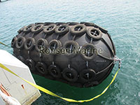
A pneumatic rubber fender works by compressing trapped compressed air inside a reinforced rubber cylinder to convert a ship’s kinetic berthing energy into increased internal air pressure and elastic rubber deformation. Because air is highly compressible, the fender absorbs large impact energy while returning a very low reaction force to the hull—then rebounds to its original shape when the load is removed.
Also called Yokohama fenders or floating pneumatic fenders, they are the global standard for ship-to-ship (STS) transfer and floating berths under ISO 17357-1:2014.
What Is a Pneumatic Rubber Fender?
A pneumatic rubber fender is a hollow, cylindrical, air-filled marine buffer built from synthetic-tire-cord-reinforced rubber layers with hemispherical ends. It floats at the waterline, tethered by slings or a chain-tire net, and rises/falls with tide and swell without fixed mounting.
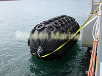
Key identifiers:
- Internal medium: compressed air (initial 50 kPa = P50, or 80 kPa = P80)
- Body: outer rubber + synthetic cord reinforcement + inner air seal
- Performance basis: 60% diameter deflection at Guaranteed Energy Absorption (GEA)
- Standard: ISO 17357-1:2014
The 4-Layer Internal Structure
LayerMaterialJobOuter rubberSynthetic NR/SBR blendAbrasion, UV, seawater, ozone resistanceCord reinforcementNylon/polyester tire cord, crossedHolds internal pressure, stops burstInner rubberAirtight linerSeals compressed air, prevents leakageEnd flange + valveSteel + safety relief valveInflation, pressure check, over-pressure release (mandatory ≥Ø2500 mm)
The cord layer is the “skeleton”—same principle as a truck tire. Without it, the rubber would balloon and fail.
How Pneumatic Fenders Absorb Energy (Step by Step)
- Vessel approaches → fender floats at hull contact point.
- Hull presses → fender compresses axially up to 60% of original diameter.
- Air column shortens → internal pressure rises uniformly (P50 or P80 baseline + impact spike).
- Kinetic energy converts → E = \frac{1}{2}mv^2 becomes internal air pressure + rubber/cord elastic strain.
- Reaction force stays low → because air compresses progressively, hull sees soft cushioning, not a hard wall.
- Vessel retreats → air re-expands, rubber rebounds elastically, fender ready for next hit (no break-in cycle needed, unlike solid rubber).
Under ISO 17357 parallel compression test, EA is the integral of reaction force over deflection:
a = \int R(x)\,dx , measured to 60% deflection at ≤80 mm/min.
Why Reaction Force Stays Low (The Core Advantage)
Solid rubber fenders fight the hull with material stiffness. Pneumatic fenders fight with gas compressibility.
Air has no fixed shape and no high initial modulus—so the force-deflection curve rises gently at first, then steeper near 60%. That “soft entry” is why pneumatic fenders show:
- High EA (e.g. Ø3300×6500 mm P80 ≈ 3015 kJ at GEA)
- Low hull pressure (P50 often 130–150 kN/m² class)
- Minimal structural stress on LNG, VLCC, and thin-shell hulls
P50 vs P80: Tuning by Air Pressure
You do not change the size—you change the initial inflation pressure.
RatingInitial pressureEA at 60% defl.Reaction forceTypical useP5050 kPaBaseline (GEA)LowestStandard STS, mid-size vesselsP8080 kPa~1.3–1.5× P50HigherVLCC/LNG, high-energy berthing
Higher pressure = more EA, but pushes more reaction force back to hull and dolphin—so P80 must be matched to hull allowable pressure.
Pneumatic vs Foam-Filled Fender (Working Principle)
AspectPneumatic rubber fenderFoam-filled fenderEnergy mediumCompressed airClosed-cell foam compressionDeflation riskYes (skin/valve breach)NoneReaction forceVery lowModerate–higherAngled impactUniform pressure (fluid air)Slightly less uniformMaintenancePressure checks, valveNoneTransportDeflatable, compactBulky, solidBest fitSTS, offshore, tide swingsFixed berths, unmanned, debris risk
Source synthesis.
Where Pneumatic Rubber Fenders Are Specified
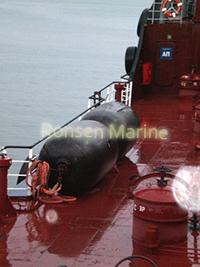
- Ship-to-ship transfer (crude, LNG, product tankers)
- Offshore platform / FPSO boat landing
- Tidal jetties and ferry terminals
- Naval alongside replenishment
- Emergency berthing where no fixed fender exists
Sizing Reminder (So the Physics Matches the Berth)
Select by design berthing energy, not boat length:
- Vessel displacement + approach velocity
- PIANC WG-211 energy model
- ISO 17357 GEA at 60% deflection
- Hull allowable pressure → pick P50 or P80
- Check reaction force against dolphin/wharf limit
A 2000×3500 mm P50 fender ≈ 875 kJ EA / 128 kN/m² hull pressure—then you verify RF fits the structure.
FAQ
How does a pneumatic fender absorb energy without solid foam?
It compresses sealed air inside a cord-reinforced rubber body; the air pressure rise plus rubber elasticity stores the vessel’s kinetic energy and releases it on rebound.
What is the difference between P50 and P80 pneumatic fenders?
P50 is inflated to 50 kPa initial pressure, P80 to 80 kPa. P80 gives 30–50% more energy absorption but higher reaction force on the hull.
Do pneumatic fenders need maintenance?
Yes—regular air-pressure checks (cold/warm drift), valve inspection, and net/sling wear checks. Foam fenders do not.
Can a pneumatic fender explode?
Not under normal use; ISO units ≥2.5 m carry automatic safety relief valves. Burst risk comes from over-inflation, fire, or ignored valve failure.
Why are they called Yokohama fenders?
The Yokohama Rubber Co. commercialized the floating air-filled design in the 1950s; “Yokohama-type” is now synonymous with pneumatic rubber fender.

